


")
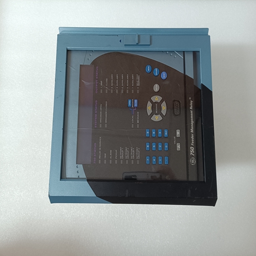
SR750-P5-G5-S5-HI-A20-R-T继电器
设置跳线如果使用RS-232以外的接口(默认),则必须更改跳线配置以匹配接口。有三个跳线位于模块底部。下图显示了MVI56-101M跳线配置:1设置PRT 2(用于应用程序端口1)和PRT 3(用于应用软件端口2)用于RS232、RS422或RS485的跳线,以匹配您的应用两个应用程序端口的默认跳线设置为RS-232。2设置跳线用作模块闪存的“写保护”。在“写保护”模式下,设置引脚未连接,并且模块的固件不能被覆盖。不要跨接设置引脚除非ProSoft技术支持部门指示您这样做。在机架中安装模块
如果尚未安装和配置ControlLogix处理器,以及电源,请在安装MVI56-101M模块之前进行此操作。提到有关安装说明,
请参阅罗克韦尔自动化产品文档。
警告:安装本电子设备或任何其他电子设备时,必须遵守所有安全说明设备。不遵守安全程序可能导致硬件或数据损坏,甚至人员重伤或死亡。请参阅您计划使用的每个设备的文档在安装或维修之前,连接以验证适当的安全程序是否到位装置
检查跳线位置后,将MVI56-101M插入ControlLogix机箱。使用罗克韦尔推荐的相同技术
自动移除和安装ControlLogix模块。警告:当背板电源接通时插入或移除模块时,会出现电弧
这可能发生。这可能导致危险场所设施爆炸。验证电源是否为在继续之前,移除或该区域无危险。重复电弧原因模块及其配合连接器上的触点过度磨损。磨损的触点可能产生可能影响模块操作的电阻。
1关闭电源。
2将模块与顶部和底部导轨对齐,并将其滑入机架直到模块牢固地抵靠背板连接器。
Setting Jumpers
If you use an interface other than RS-232 (default), you must change the jumper
configuration to match the interface. There are three jumpers located at the
bottom of the module.
The following illustration shows the MVI56-101M jumper configuration: 1 Set the PRT 2 (for application port 1) and PRT 3 (for application port 2)
jumpers for RS232, RS422, or RS485 to match the wiring needed for your
application. The default jumper setting for both application ports is RS-232.
2 The Setup Jumper acts as "write protection" for the module’s flash memory.
In "write protected" mode, the Setup pins are not connected, and the
module’s firmware cannot be overwritten. Do not jumper the Setup pins
together unless you are directed to do so by ProSoft Technical Support. Installing the Module in the Rack
If you have not already installed and configured your ControlLogix processor and
power supply, please do so before installing the MVI56-101M module. Refer to
your Rockwell Automation product documentation for installation instructions.
Warning: You must follow all safety instructions when installing this or any other electronic
devices. Failure to follow safety procedures could result in damage to hardware or data, or even
serious injury or death to personnel. Refer to the documentation for each device you plan to
connect to verify that suitable safety procedures are in place before installing or servicing the
device.
After you have checked the placement of the jumpers, insert MVI56-101M into
the ControlLogix chassis. Use the same technique recommended by Rockwell
Automation to remove and install ControlLogix modules. Warning: When you insert or remove the module while backplane power is on, an electrical arc
can occur. This could cause an explosion in hazardous location installations. Verify that power is
removed or the area is non-hazardous before proceeding. Repeated electrical arcing causes
excessive wear to contacts on both the module and its mating connector. Worn contacts may
create electrical resistance that can affect module operation.
1 Turn power OFF.
2 Align the module with the top and bottom guides, and slide it into the rack
until the module is firmly against the backplane connector.

