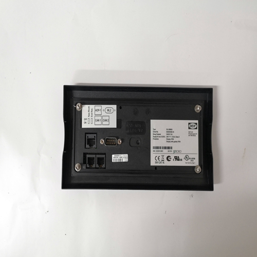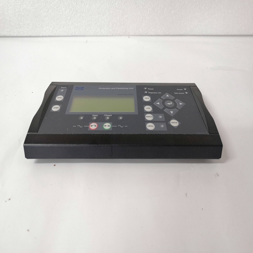
DEIF DU-2/MKIII控制屏
预防性维护DECS-100所需的唯一预防性维护是定期检查连接DECS-100和系统之间的清洁和紧密。DECS-100装置的制造使用:最先进的表面贴装技术。因此,Basler Electric建议不进行维修除Basler Electric人员外,任何人都可以尝试该程序。
故障排除如果您没有从DECS-100获得预期的结果,首先检查可编程设置适当的功能。遇到困难时,请使用以下故障排除步骤在励磁系统的运行中。
发电机电压不建立步骤1.验证所有接线是否正确连接。参见图4-6至图4-10。
如果接线连接不当或松动,请正确重新连接接线。如果接线正确,则转至步骤2。
步骤2.验证发电机是否以额定转速旋转。
如果发电机未达到额定转速,则将发电机转速增加至额定值。
如果发电机以额定转速旋转,则转至步骤3。步骤3.对于PMG电源,检查DECS-100的输入电源是否正确。参考第1节,概述输入功率要求的信息和规范。检查DECS-100端子B1和B3上的公用参考电压是否正确。如果互连不正确,请根据相应的互连图重新连接。如果互连正确,检查系统保险丝是否开路。
验证电位传感变压器(如使用)是否连接至DECS-100端子B1和B3。
如果电位感应变压器连接正确,则转至步骤5。步骤5.验证发电机输出电压设定值是否在测量公用母线的10%以内电压如果设定值过低或过高,则将设定值调整到适当的水平。
如果设定值正确,则转至步骤6。步骤6.如果上述步骤未能纠正电压匹配故障,则更换DECS-100。
PREVENTATIVE MAINTENANCE
The only preventive maintenance required on the DECS-100 is to periodically check that the connections
between the DECS-100 and the system are clean and tight. DECS-100 units are manufactured using
state-of-the-art, surface-mount technology. As such, Basler Electric recommends that no repair
procedures be attempted by anyone other than Basler Electric personnel.
TROUBLESHOOTING
If you do not get the results that you expect from the DECS-100, first check the programmable settings for
the appropriate function. Use the following troubleshooting procedures when difficulties are encountered
in the operation of your excitation system.
Generator Voltage Does Not Build
Step 1. Verify that all wiring is properly connected. Refer to Figures 4-6 through 4-10.
If wiring is improperly connected or loose, reconnect wiring properly.
If wiring connections are correct, proceed to Step 2.
Step 2. Verify that the generator is spinning at rated speed.
If the generator is not up to rated speed, increase generator speed to the rated value.
If the generator is spinning at rated speed, proceed to Step 3.
Step 3. For PMG power, check for correct input power to the DECS-100. Refer to Section 1, General
Information, Specifications for input power requirements. Check for correct utility reference voltage on DECS-100 terminals B1 and B3.
If the interconnection is incorrect, reconnect according to the appropriate interconnect diagram.
If the interconnection is correct, check for open system fuses.
Verify that the potential sensing transformer, if used, is connected to DECS-100 terminals B1
and B3.
If potential sensing transformer connections are correct, proceed to Step 5.
Step 5. Verify that the generator output voltage setpoint is within 10 percent of the measured utility bus
voltage.
If the setpoint is too low or too high, adjust the setpoint to the appropriate level.
If the setpoint is correct, proceed to Step 6.
Step 6. If the above steps fail to correct the Voltage Matching malfunction, replace the DECS-100.


