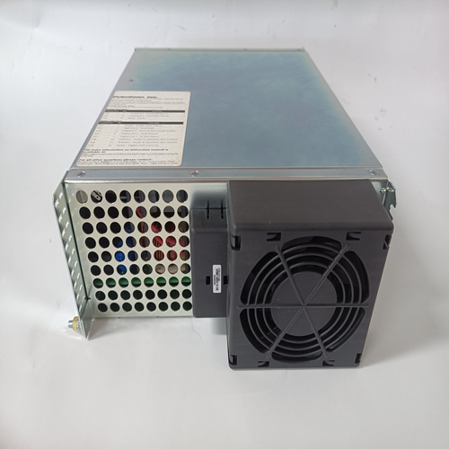
Kollmorgen S72402-NANANA驱动器
前面板指示器
八个前面板LED指示灯指示各种保护功能和操作模式。
第2节人机界面提供了有关前面板指示器的更多信息。
继电器输出通过端子AL1和AL2提供一个公共报警输出触点触点指示报警或跳闸条件。继电器输出为非锁存。
DECS-100操作特性以下段落描述了每个DECS-100操作特性。
模式DECS-100提供多达四种可通过BESTCOMS软件选择的操作模式。自动电压调节模式和手动模式是标准功能。无功功率因数模式是一种选择。
自动电压调节模式
在自动电压调节(AVR)模式下,DECS-100调节rms发电机输出电压。这是通过感应发电机输出电压和调整直流输出励磁电流来实现的将电压保持在调节设定值。调节设定点通过升高和降低触点输入、附件输入或通过BESTCOMS软件进行调整。调节点也可以是:在某些条件下由下垂函数或低频函数修改。
手动模式
在手动模式下,也称为磁场电流调节(FCR)模式,DECS-100维持直流设定水平的励磁电流。电流电平设定值可在0.1 Adc中从0到7 Adc进行调整通过升高和降低触点输入、可选附件输入或通过BESTCOMS递增
软件在Var控制模式下,DECS-100在以下情况下将发电机Var(伏安、无功)保持在设定水平与无限总线并联。DECS-100通过使用感测的发电机计算发电机VAR输出电压和电流量。然后调整直流励磁电流,以将VAR保持在设定点。Var控制通过BESTCOMS软件启用和禁用。当软件打开时接通时,通过var/功率因数控制(52J/K)触点输入电路启用或禁用var控制。
var设定值可通过提升和调节
从100%吸收到100%发电低触点输入、可选附件输入或通过BESTCOMS软件。
功率因数控制模式(可选)
在功率因数控制模式下,DECS-100在以下情况下将发电机功率因数保持在设定水平与无限总线并联。DECS-100使用感测的数据计算发电机功率因数发电机输出电压和电流量,然后调整直流励磁电流以维持设定点的功率因数。功率因数控制通过BESTCOMS软件启用或禁用。当软件打开时,通过Var/功率因数控制(52J/K)启用或禁用接触输入电路。功率因数设定值可在0.6滞后和0.6超前之间调整升高和降低触点输入、可选附件输入或通过BESTCOMS软件。
Front Panel Indicators
Eight front-panel LED indicators light to indicate various protective functions and operating modes.
Section 2, Human-Machine Interface provides more information about the front panel indicators.
Relay Output
A common alarm output contact is provided through terminals AL1 and AL2. This normally open, form A
contact annunciates alarm or trip conditions. The relay output is non-latching.
DECS-100 OPERATING FEATURES
The following paragraphs describe the characteristics of each DECS-100 operating feature.
Operating Modes
The DECS-100 provides up to four modes of operation selectable through BESTCOMS software.
Automatic voltage regulation mode and Manual mode are standard features. Var and Power Factor
modes are an option.
Automatic Voltage Regulation Mode
In Automatic Voltage Regulation (AVR) mode, the DECS-100 regulates rms generator output voltage.
This is accomplished by sensing generator output voltage and adjusting dc output excitation current to
maintain voltage at the regulation setpoint. The regulation setpoint is adjusted by the Raise and Lower contact inputs, the Accessory input, or through BESTCOMS software. The regulation point may also be
modified by the Droop function or the Underfrequency function under certain conditions.
Manual Mode
In Manual mode, also known as Field Current Regulation (FCR) mode, the DECS-100 maintains dc
excitation current at a set level. The current-level setpoint is adjustable from 0 to 7 Adc in 0.1 Adc
increments by the Raise and Lower contact inputs, the optional Accessory input, or through BESTCOMS
software. In Var Control mode, the DECS-100 maintains generator vars (volt-amperes, reactive) at a set level when
paralleling with an infinite bus. The DECS-100 calculates generator vars by using the sensed generator
output voltage and current quantities. It then adjusts the dc excitation current to maintain vars at the
setpoint. Var control is enabled and disabled through BESTCOMS software. When the software is turned
on, var control is enabled or disabled through the Var/Power Factor Control (52J/K) contact input circuit.
The var setpoint is adjustable from 100 percent absorb to 100 percent generate through the Raise and
Lower contact inputs, the optional Accessory input, or through BESTCOMS software.
Power Factor Control Mode (Optional)
In Power Factor Control mode, the DECS-100 maintains generator power factor at a set level when
paralleling with an infinite bus. The DECS-100 calculates generator power factor using the sensed
generator output voltage and current quantities and then adjusts the dc excitation current to maintain
power factor at the setpoint. Power factor control is enabled or disabled through BESTCOMS software.
When the software is turned on, it is enabled or disabled through the Var/Power Factor Control (52J/K)
contact input circuit. The power factor setpoint is adjustable between 0.6 lag and 0.6 lead through the
Raise and Lower contact inputs, the optional Accessory input, or through BESTCOMS software.


