


主营产品
PLC可编程控制器模块,DCS卡件,ESD系统卡件,振动监测系统卡件,汽轮机控制系统模块,燃气发电机备件等,优势品牌:Allen Bradley、BentlyNevada、ABB、Emerson Ovation、Honeywell DCS、Rockwell ICS Triplex、FOXBORO、Schneider PLC、GE Fanuc、Motorola、HIMA、TRICONEX、Prosoft等各种进口工业零部件
产品广泛应用于冶金、石油天然气、玻璃制造业、铝业、石油化工、煤矿、造纸印刷、纺织印染、机械、电子制造、汽车制造、塑胶机械、电力、水利、水处理/环保、锅炉供暖、能源、输配电等等
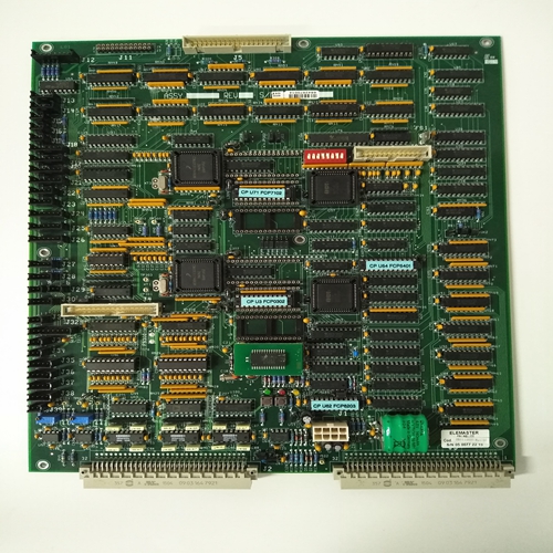
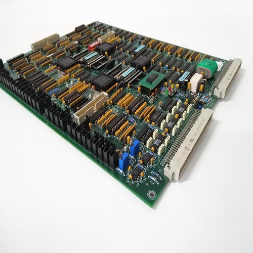
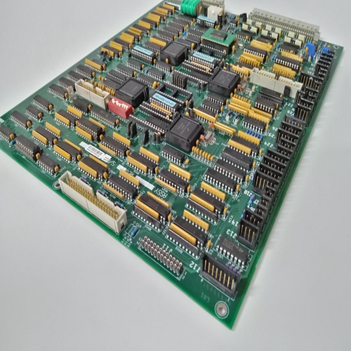
ELEMASTER IB3110551工控模块
所有软件配置,即保护功能的选择和设置以及输入和通过RS-423串行接口在216VC62a处理单元。相应的连接器是装置前部的25针插座X2,个人计算机已连接。
2.2.2.216MB66型设备机架布局图2.2显示了电子设备的布置示例设备机架中的单元。设备机架被细分
分成21个分部(T)。第1-3部分和第19-21部分始终用于:辅助直流电源装置216NG61、216NG62或216NG63原则上,如果系统电缆连接已相应安装,则电子单元可位于剩余的分区4-18中的任何分区中。然而,出于标准化的原因,各种类型的装置始终位于设备机架中的同一位置。有关特定工厂216MB66设备机架中电子单元的布局,请参阅特定的一组图表。
表2.1给出了各种装置的标准槽参考。
例如,最多两个216VC62a处理单元可以安装在设备机架中,并始终位于插槽中4和6。
I/P的I/O信号的名称和编号
保护系统的O/P单元在“I/O”列中给出通道定义”。请注意,给定的I/O通道数量
对于每组相同类型的装置,指的是设备机架,而不是整个系统。总数量
整个系统的I/O通道由I/O数量给出已安装的机组(另见第2.2.3节和一组特定设备图)替代系统版本
保护中使用的电子单元和I/O单元的数量系统根据工厂要求而变化。最大值
一个系统中的电子单元数量(单个216MB66设备机架)如表2.1所示。
表中列出的版本的I/O信号数量
2.2至表2.4,指完整系统(单个系统一个216MB66设备机架)。设备机架可容纳一个或两个216VC62a处理单元,因此表2.2至表2.4中给出的版本总计计算能力为425%或850%。
All software configuration, i.e. selection and setting of the protection functions and the assignment of signals to the inputs and
outputs, is performed via the RS-423 serial interface on the
216VC62a processing unit. The corresponding connector is the
25 pin socket X2 on the front of the unit, to which a personal
computer is connected.
2.2.2. Layout of equipment rack Type 216MB66
Fig. 2.2 shows an example of the arrangement of the electronic
units in the equipment rack. The equipment rack is sub-divided
into 21 divisions (T). Divisions 1-3 and 19-21 are always used for
auxiliary d.c. supply units 216NG61, 216NG62 or 216NG63. In
principle, the electronic units may be located in any of the remaining divisions 4-18, providing that the system cable connections were correspondingly installed. For reasons of standardisation, however, the various types of units are always located at the same position in the equipment rack.Consult the specific set of diagrams for the layout of the electronic units in the 216MB66 equipment rack of a particular plant.
Table 2.1 gives the standard slot references for the various units.
For example, a maximum of two 216VC62a processing units can
be installed in an equipment rack and are always located in slot
4 and 6.
The designations and numbering of the I/O signals for the I/P
and O/P units of a protection system are given in the column "I/O
channel definition". Note that the quantity of I/O channels given
for each group of the same type of units refers to the particular
equipment rack and not the entire system. The total quantity of
I/O channels for the entire system is given by the number of I/O
units installed (see also Section 2.2.3. and the set of specific
plant diagrams)Alternative system versions
The number of electronic units and I/O units used in a protection
system varies according to plant requirements. The maximum
quantities of electronic units in one system (a single 216MB66
equipment rack) are given in Table 2.1.
The numbers of I/O signals given for the versions listed in Table
2.2 to Table 2.4 refer to a complete system (single system with
one 216MB66 equipment rack). An equipment rack can accommodate one or two 216VC62a processing units and therefore the
versions given in Table 2.2 to Table 2.4 can have a total
computing capacity of 425% or 850%.

