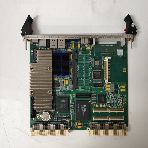
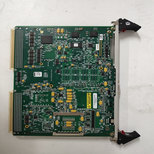
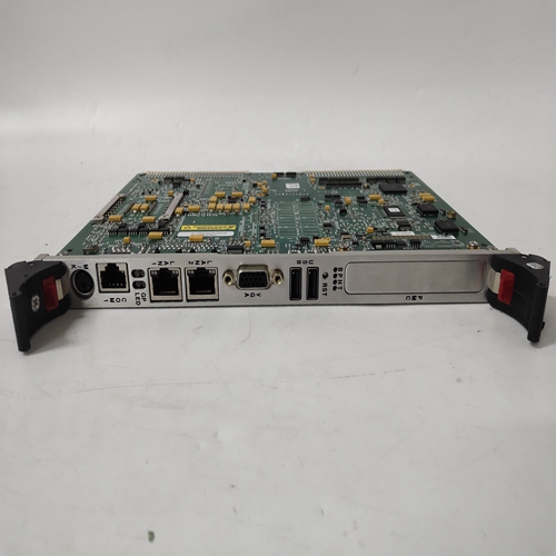
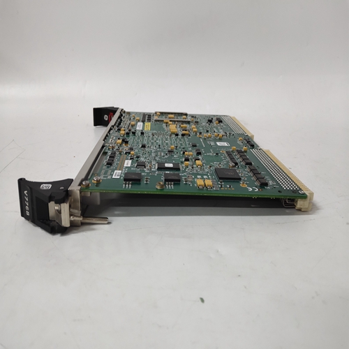
GE 350-9301007768-322001 A2,燃机通用电气模块
在不模拟过程信号但增加数字滤波器的情况下,很难模拟自动调谐特性AIN1上的参数将有助于使过程看起来更现实。要将数字滤波器更改为值:大约10按照第2节中的配置路线图或执行以下步骤。
1.按ENTER/EXIT CONF。
2.按两次“向下”以显示视图。
3.使用右箭头按钮或脉冲发生器旋钮显示编辑FB。
4.按下“功能块菜单”的“下一步”。
5.使用右箭头按钮或脉冲发生器旋钮显示AIN1。
6.按下“参数菜单”下的“步进”。
7.使用右箭头按钮或脉冲发生器旋钮显示DIG FILT,然后按下STEP DOWN。
8.旋转脉冲发生器旋钮,将数字滤波器设置为10,然后按存储。
9.按ENTER/EXIT CONF返回正常操作。
在启动自动调谐之前,使过程处于稳定状态
这可以通过将仪器放置在手动模式,并使用脉冲发生器旋钮将阀门调至大约中间刻度。显示过程和等待一两分钟,等待过程稳定下来。要激活自动调谐功能:
1.按下调谐快速按钮以显示自动调谐。
2.将此参数设置为是,按存储,然后按退出。控制器现在设置为自动,并且“自动调谐”将闪烁,直到自动调谐完成。可能出现调谐警告;参见第9.3节。由于这只是一个模拟,请按确认以清除任何警告。
3.按下调谐按钮以显示默认控制器参数和产生的自动调谐(ATUNE)参数。查看参数后,将显示存储地址。按存储按钮进行更改将控制器参数设置为新值,或按ENTER/EXIT CONF按钮保持默认值。要在调谐操作完成前取消自动调谐,请按A/M按钮进入手动模式。有关自动调谐功能的更多详细信息,请参阅第9.3节。10.1.10查看模式在对配置进行故障排除时,能够查看功能的中间输出通常很有帮助正常操作期间未配置为显示变量的块。这可以通过查看模式。
要进入查看模式:
1.按ENTER/EXIT CONF以显示循环。
2.按“下一步”以显示视图。
3.按下降压键以显示第一个配置功能块的第一个输出。
4.使用脉冲发生器旋钮或箭头按钮滚动功能块输出。请注意,模拟输出为:
工程单位和离散/状态输出(由功能块中的黑色阴影箭头表示图表)为低(0)或高(1)。
5.按退出返回正常操作模式。
It is difficult to simulate the autotune feature without simulating a process signal but increasing the digital filter
parameter on the AIN1 will help make the process seem more realistic. To change the digital filter to a value
around 10 follow the Configuration Road Map in Section 2 or do the following steps.
1. Press ENTER/EXIT CONF.
2. Press STEP DOWN twice to display VIEW.
3. Use the right arrow button or the pulser knob to display EDIT FB.
4. Press STEP DOWN for Function Block menu.
5. Use the right arrow button or the pulser knob to display AIN1.
6. Press STEP DOWN for parameter menu.
7. Use the right arrow button or the pulser knob to display DIG FILT and Press STEP DOWN.
8. Rotate the pulser knob to set the digital filter to 10 and press STORE.
9. Press ENTER/EXIT CONF to return to normal operation.
Before initiating AUTOTUNE bring the process to steady state. This can be done by placing the instrument in
manual mode and bringing the valve to approximately mid-scale using the pulser knob. Display the process and
wait a minute or two for the process to stabilize.
To activate the AUTOTUNE feature:
1. Press the TUNE Quick Button to display AUTOTUNE.
2. Set this parameter to YES, press STORE, then press EXIT. The controller is now set to AUTO and
“AUTOTUNE” will flash until the AUTOTUNE is finished. Tuning warnings may occur; refer to Section 9.3.
Since this is only a simulation, press ACK to clear any warnings.
3. Press the TUNE button to display the default controller parameters and the resulting AUTOTUNE (ATUNE)
parameters. After viewing the parameters, STORE AT will be displayed. Press the STORE button to change
the controller parameters to the new values or press the ENTER/EXIT CONF button to keep the defaults.
To cancel the AUTOTUNE before the tuning operation is complete, press the A/M button to enter MANUAL mode.
Refer to Section 9.3 for more details on the AUTOTUNE feature. 10.1.10 View mode
When troubleshooting a configuration, it is often helpful to be able to view the intermediate outputs of function
blocks that are not configured as display variables during normal operation. This can be accomplished via the
VIEW mode. To enter VIEW mode:
1. Press ENTER/EXIT CONF to display LOOP.
2. Press STEP DOWN to display VIEW.
3. Press STEP DOWN to display the first output of the first configured function block.
4. Use the pulser knob or arrow buttons to scroll through the function block outputs. Note that analog outputs are
in engineering units and discrete/status outputs (represented by the black shaded arrows in the Function Block
diagrams) are either low (0) or high (1).
5. Press EXIT to return to normal operation mode.


