


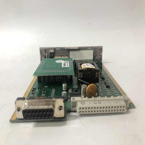
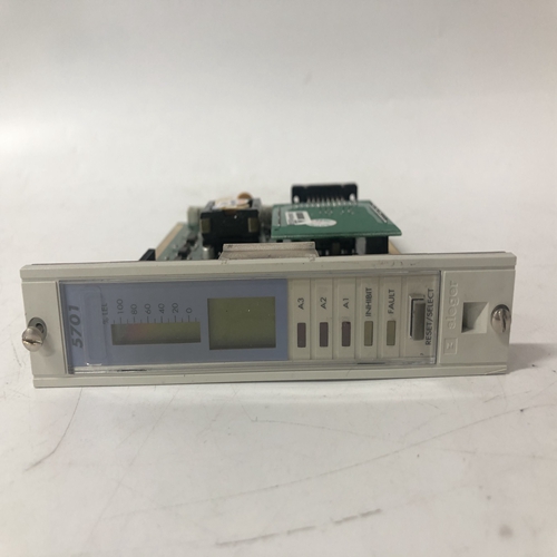
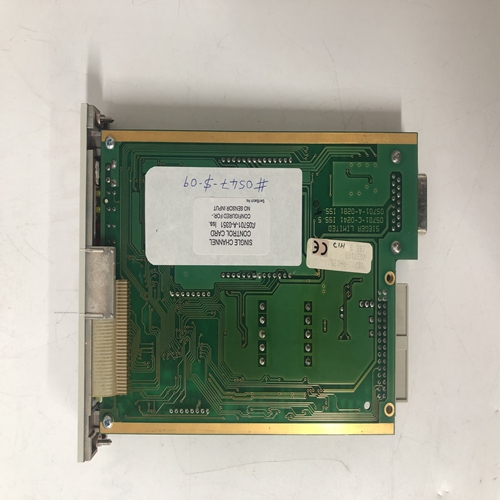
HONEYWELL 05704-A-0121逻辑卡件
功能块AINU1和AINU2可配置为热电偶或RTD输入。
热电偶输入接线如图8-16所示。所示为典型的接地端热电偶。如果
如果使用不接地热电偶,热电偶线屏蔽可在Moore 353处接地。热电偶导线通常有实心导体。按照第8.4.2节所述进行连接。确保实心导体:通过端子螺钉和压板令人满意地夹紧。中提供了两个参考结(RJ)
I/O扩展器板安装套件。按如下所述进行安装。热电偶参考接头(RJ)安装:
1.将一段绝缘套管滑到每个参考连接导线的将保持暴露的部分上安装后。小心地形成如下所示的引线。2.注意连接器类型,并使用带有1/8英寸(3mm)叶片宽度。将参考接线引线插入连接器相邻侧的两个开口中到所选的终端号码。按照当前连接器类型的说明定位参考接头。
1) 直插式连接器-小心地向下压连接器之间的参考接头。3.检查所有相关部件和站接线是否完全插入。小心拧紧端子螺钉至5英寸。磅。
4.如果将另一个AINU功能块用作热电偶输入,则重复上述步骤。
8.4.6 RTD输入接线
2线、3线和4线RTD的接线如图8-18所示。按照第8.4.3节所述进行连接。注
安装2线电阻式温度检测器时,端子47和48之间的跨接导线。8.4.7欧姆和滑线输入接线
功能块AINU1和AINU2可配置为欧姆或滑动线输入。图8-19和8-20显示:所需的连接。
8.4.8继电器输出接线
功能块ROUT1和ROUT2位于I/O扩展器板上。它们提供两个单极,双掷继电器输出,如图8-21所示。继电器触点额定值见第14.6节。
连接到闭合触点的负载应在最小和最大触点额定值之间汲取电流。
建议使用电阻负载。电感性或电容性负载可能导致峰值电流或接触电弧这会凹坑或以其他方式损坏触点。与感应负载相关的电弧可通过以下方式进行限制:在负载两端连接电压瞬变抑制器,如1N4005二极管。8.4.9就地仪表链路接线本地仪表链路(LIL)是一种高性能数字数据链路,承载命令和响应在用户选择的站之间。每个站必须由唯一的链路地址标识。这个地址允许从一个站发送到另一个特定站的命令和响应。较低的链路地址为1到32.321型扩展卫星用于添加具有地址33至64的上行链路。在摩尔353中,站地址作为地址参数输入STATN功能块。有关在其他型号中设置链接地址的具体说明,请参阅该型号的安装和服务说明模型有关本地仪表链路的完整安装、接线和维修说明,请参阅SD15492。
Function blocks AINU1 and AINU2 can be configured for thermocouple or RTD input.
Thermocouple input wiring is shown in Figure 8-16. Shown is a typical grounded tip thermocouple. If an
ungrounded thermocouple is used, the thermocouple wire shield can be grounded at the Moore 353. Thermocouple
wire often has a solid conductor. Make connections as outlined in Section 8.4.2. Be sure that the solid conductor is
satisfactorily clamped by the terminal screw and pressure plate. Two reference junctions (RJ) are supplied in the
I/O Expander board installation kit. Install as outlined below. Thermocouple reference junction (RJ) installation:
1. Slip a length of insulating sleeving over the portion of each reference junction lead that will remain exposed
after installation. Carefully form the leads as shown below.2. Note the connector type and loosen the two terminal screws using a straight blade screwdriver with a 1/8″ (3
mm) blade width. Insert the reference junction leads into the two openings in the side of the connector adjacent
to the selected terminal numbers. Position the Reference Junction as described for the connector type at hand.
1) Direct Entry Connector - Carefully press the reference junction down between the connectors.3. Check that all involved components and station wiring are fully inserted. Carefully tighten the terminal screws
to 5 in. lbs.
4. Repeat the above steps if the other AINU function block is to be used as a thermocouple input.
8.4.6 RTD Input Wiring
Wiring for 2-, 3-, and 4-wire RTDs is shown in Figure 8-18. Make connections as outlined in Section 8.4.3. Note
the wire jumper between terminals 47 and 48 when a 2-wire RTD is installed. 8.4.7 Ohms and Slidewire Input Wiring
Function blocks AINU1 and AINU2 can be configured for ohm or slidewire inputs. Figures 8-19 and 8-20 show
the needed connections.
8.4.8 Relay Output Wiring
Function blocks ROUT1 and ROUT2 are located on the I/O Expander board. They provide two single-pole,
double-throw relay outputs, as shown in Figure 8-21. Relay contact ratings are stated in Section 14.6.
The load connected to a closed contact should draw a current between the minimum and maximum contact ratings.
A resistive load is recommended. An inductive or capacitive load can cause high peak currents or contact arcing
which can pit or otherwise damage contacts. The arcing associated with an inductive load can be limited by
connecting a voltage transient suppressor, such as a 1N4005 diode, across the load. 8.4.9 Local Instrument Link Wiring
The Local Instrument Link (LIL) is a high performance digital data link that carries commands and responses
between user-selected stations. Each station must be identified by a unique link address. This address permits
commands and responses to be sent from one station to another specific station. Lower link addresses are 1 through
32. A Model 321 Expansion Satellite is used to add an upper link with addresses 33 through 64. In the Moore 353,
the Station address is entered as the ADDRESS parameter in the STATN function block. Specific instructions for setting a link address in other models are available in the Installation And Service Instructions for that particular
model. Refer to SD15492 for complete installation, wiring, and service instructions for the Local Instrument Link.

