


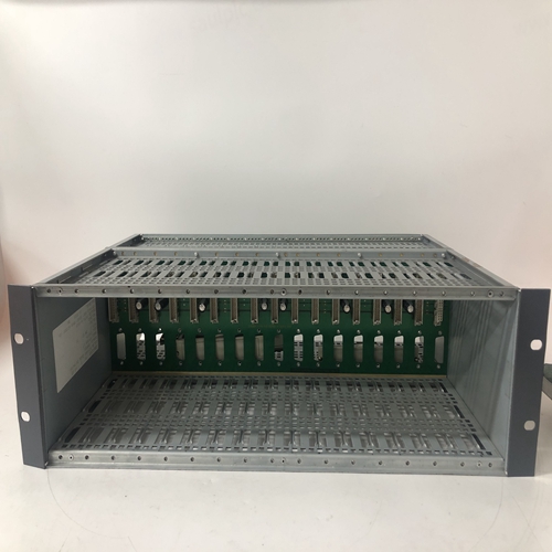
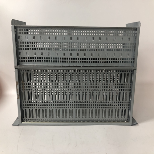
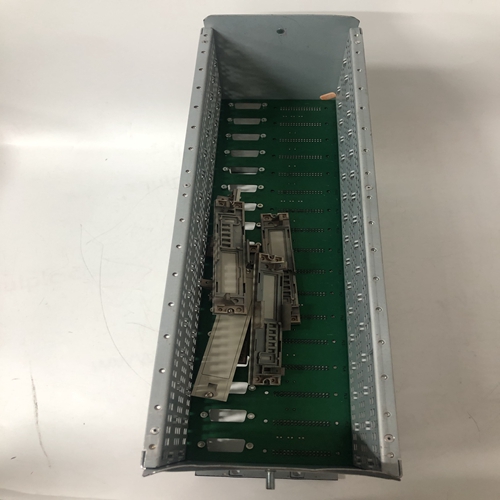
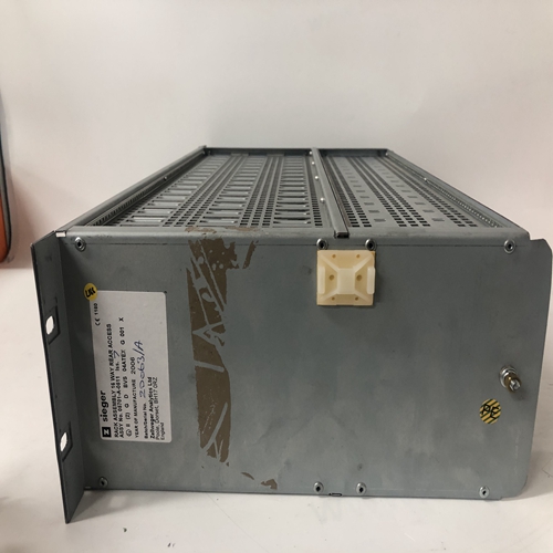
HONEYWELL 05701-A-0511逻辑框架
提供压接连接器,用于将量程电阻器和信号输入线插入
相同的连接器端子。当两条不同规格的导线会出现以下情况时,也应使用连接器:否则可插入单个连接器端子中。对每个模拟输入执行以下步骤。
1.选择模拟输入端子对,用于连接输入信号布线。参考表8.1和如有必要,请参见下图。
对于4-20 mA输入,请转至步骤2。对于1-5 Vdc或毫伏输入,请转到步骤4。仅4-20毫安输入-选择250Ω (对于AIN#)或3.75Ω (适用于阿伊努#)安装套件中的电阻器,并用一块将弯曲的电阻器引线绝缘指袖子。在引线端,约1/4英寸(6毫米)至5/16英寸(8毫米)裸露的电阻引线应露出。
如果要使用压接接头,则转至步骤3。否则,转至步骤4。3.压接接头-将电阻引线和任何信号线插入接头,直到导线端在接头的针脚端可见。使用标准电气接头压接工具压接连接。是确保所有电阻引线和信号输入线都插入压接前的连接器。
4.使用刀片宽度为1/8“(3 mm)的一字螺丝刀松开两个端子螺钉。插入导线、电阻引线或接头针脚上的压接件插入接头侧面的两个开口中选择的终端号码。
5.检查所有相关部件和站接线是否完全插入,并小心地将螺钉拧紧至5在里面磅。不要过度拧紧。
6.对每个4-20 mA、1-5 Vdc和毫伏输入重复步骤1-5。
7.小心地修整电阻器和接线,以便不会在部件、导线或连接上施加过大的应力。
8.4.3模拟输出接线(4-20 mA,1-5 Vdc)
模拟输出功能块为AOUT1、AOUT2和AOUT3。图8-12显示了外部
接受4-20 mA的设备。对于需要1-5 Vdc的外部设备,请参见图8-13。参考第8.4.2节接线指南。
8.4.4数字输入和输出接线
数字输入和数字输入通用功能块的连接如图8-14所示
显示了内部和外部电源。半导体器件可以代替所示的机械开关。
布线指南见第8.4.2节。
数字输入共用线,例如DIN1(-)与站公用线和外壳/安全接地隔离。
数字输出接线如图8-15所示。提供了三个电流和电压输出图。
注意图8-15C中瞬态抑制二极管的使用。始终安装瞬态抑制部件
以保护摩尔353中的半导体器件。
数字输出公共线DOUTC连接到站公共线。
Crimp-on connectors are provided for use when a range resistor and a signal input wire are to be inserted in the
same connector terminal. A connector should also be used when two wires of significantly different gauges would
otherwise be inserted in a single connector terminal.
Perform the following steps for each analog input.
1. Select an analog input terminal pair for connection of the input signal wiring. Refer to Table 8.1 and the
following illustrations as necessary.
For a 4-20 mA input, go to step 2. For a 1-5 Vdc or millivolt input, go to step 4. 4-20 mA Input Only - Select a 250Ω (for AIN#) or 3.75Ω (for AINU#)
resistor from the installation kit and insulate the bent resistor lead with a piece
of sleeving. At the lead end, approximately 1/4" (6 mm) to 5/16" (8 mm) of
bare resistor lead should be exposed.
If a crimp-on connector is to be used, go to step 3. Otherwise, go to step 4. 3. Crimp-On Connector - Insert the resistor lead and any signal wiring into the
connector until the wire ends are visible at the pin end of the connector.
Use a standard electrical connector crimp tool to crimp the connection. Be
certain that all resistor leads and signal input wires are inserted in the
connector before crimping.
4. Loosen the two terminal screws using a straight blade screwdriver with a 1/8" (3 mm) blade width. Insert
wires, resistor leads, or a crimp-on connector pin into the two openings in the side of the connector adjacent to
the selected terminal numbers.
5. Check that all involved components and station wiring are fully inserted and carefully tighten the screws to 5
in. lbs. Do not over tighten.
6. Repeat steps 1-5 for each 4-20 mA, 1-5 Vdc and millivolt input.
7. Carefully dress resistors and wiring so that excessive stress is not placed on a component, wire, or connection.
8.4.3 Analog Output Wiring (4-20 mA, 1-5 Vdc)
Analog output functions blocks are AOUT1, AOUT2, and AOUT3. Figure 8-12 shows connections for an external
device that accepts 4-20 mA. For an external device that needs 1-5 Vdc, see Figure 8-13. Refer to Section 8.4.2 for
wiring guidelines.
8.4.4 Digital Input and Output Wiring
Connections to Digital Input and Digital Input Universal function blocks are shown in Figure 8-14. Wiring for
internal and external power sources is shown. Semiconductor devices can replace the mechanical switches shown.
Wiring guidelines are found in Section 8.4.2.
Digital input commons, e.g. DIN1 (-), are isolated from station common and from case/safety ground.
Digital output wiring is shown in Figure 8-15. Three diagrams are provided showing current and voltage outputs.
Note the use of transient suppression diodes in Figure 8-15C. Always install a transient suppression component
across a reactive component, such as a relay coil, to protect the semiconductor devices in the Moore 353.
Digital output common, DOUTC, is connected to station common.

