


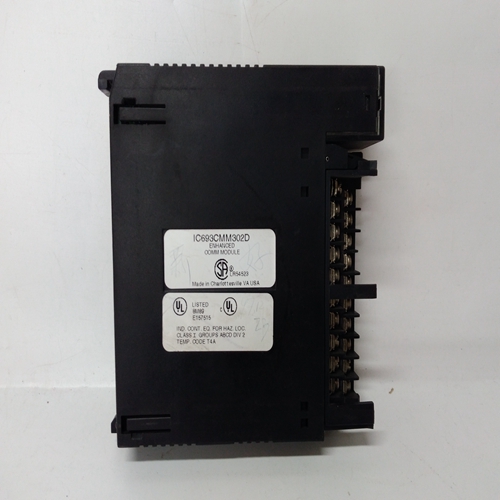
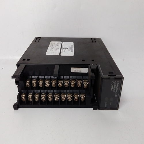
IC693CMM302可编程模块
1.识别污染物并实施减少其存在的方法。
2.为现场安装的控制器安装保护外壳。
3.清洁设备和周围区域,特别是地板时,用真空吸尘器清除所有灰尘和污垢,或
使用湿布或拖把。清扫或干燥除尘可循环灰尘和污垢。
4.定期清洁或更换所有空调过滤器、室内空气过滤器和设备过滤器。
5.通知所有接触设备的人员需要清洁。
8.3机械安装
以下小节提供了在面板或机架中安装控制器的指南和程序。这个安装应具有结构刚性,控制器应在面板或机架中呈方形。
有两种外壳连接器样式:直接入口和侧入口13。要识别外壳上的连接器样式,请参阅下表。两种样式具有相同的终端功能和编号。例如,站/发射机侧进和直进连接器上的端子6是常见的。电路板与任一连接器类型匹配。连接器样式、发货日期、分布图和插图2001年3月后直接进入-绿色或灰色
-插入式端子部分由两个螺钉固定
-包括以太网连接器
-外壳铭牌:型号353_4…14
-盖的安装和拆卸:图8-1
-面板切口:图8-3
-控制器尺寸:图8-4
-端子,见图8-7
2001年4月之前的侧面进入-黑色
-插入式端子部分通过摩擦保持
-外壳铭牌:型号353_2。。。
-拆卸连接器:图8-2
-面板切口:图8-3
-控制器尺寸:图8-5
-端子,见图8-8
8.3.1可拆卸连接器和盖
为了接近外壳安装的连接器,可能需要拆下盖子。接线时重新安装盖
完整的。如上所述,每个连接器都有一个可从外壳上分离的可拆卸部分
安装部分,接线,然后重新连接。本节将描述盖子拆卸、连接器分离以及
直接进入和侧面进入连接器类型的安装。
盖子和连接器的拆卸和安装,直接进入移动
1.从顶部向下轻轻挤压盖子约2“(5 mm),然后向上推盖子。见图8-1。出厂时,盖未安装在外壳上。
2.找到要拆卸的接头。如有必要,断开、松开或解开连接到
待拆卸的连接器。确保导线有足够的松弛度,以便拆卸接头。
3.松开将连接器可拆卸部分固定到固定部分的两个固定螺钉。
4.抓住可拆卸部分并将其从固定部分拉出。注意不要对连接件施加应力或损坏电线和部件。
1. Identify contaminants and implement methods to reduce their presence.
2. Install protective housing for field mounted controllers.
3. When cleaning equipment and surrounding area, especially the floor, either vacuum away all dust and dirt or
use a dampened rag or mop. Sweeping or dry dusting recirculates dust and dirt.
4. Clean or replace all air conditioning filters, room air filters, and equipment filters regularly.
5. Inform all personnel with access to the equipment of the need for cleanliness.
8.3 MECHANICAL INSTALLATION
The following subsections provide guidelines and procedures for mounting controllers in a panel or rack. The
installation should be structurally rigid and the controllers should be squared in the panel or rack.
There are two case connector styles: direct entry and side entry13. To identify the connector style on a case, refer to
the following table. Both styles have the same terminal functions and numbers. For example, Station/Transmitter
Common is terminal 6 on the side entry and direct entry connectors. Circuit boards mate with either connector style.
CONNECTOR STYLE DATES SHIPPED ATRIBUTES AND ILLUSTRATIONS
Direct Entry After March 2001 - Green or Gray
- Plug-in terminal portion is retained by two screws
- Ethernet connector included
- Case Nameplate: Model 353_4... 14
- Cover Installation and Removal: Figure 8-1
- Panel Cutout: Figure 8-3
- Controller Dimensions: Figure 8-4
- Terminals, See Figure 8-7
Side Entry Prior to April 2001 - Black
- Plug-in terminal portion is retained by friction
- Case Nameplate: Model 353_2...
- Removing a Connector: Figure 8-2
- Panel Cutout: Figure 8-3
- Controller Dimensions: Figure 8-5
- Terminals, See Figure 8-8
8.3.1 Removable Connectors and Covers
To gain access to the case mounted connectors, a cover may need to be removed. Reinstall the cover when wiring is
completed. As discussed above, each connector has a removable portion that can be separated from the case
mounted portion, wired, and then reattached. This section will describe cover removal, connector separation, and
installation for both the direct entry and the side entry connector types.
COVER AND CONNECTOR REMOVAL AND INSTALLATION, DIRECT ENTRY
Removal
1. Squeeze the cover slightly about 2" (5 mm) down from the top and push the cover upward. See the Figure 8-1.
As shipped from the factory, the cover is not installed on the case.
2. Locate the connector to be removed. As necessary, disconnect, unclamp, or unbundle wires connected to the
connector to be removed. Be sure there is sufficient slack in the wiring for connector removal.
3. Loosen the two captive screws securing the removable portion of the connector to the fixed portion.
4. Grasp the removable portion and pull it from the fixed portion. Be careful not to stress or damage connected
wires and components.

