


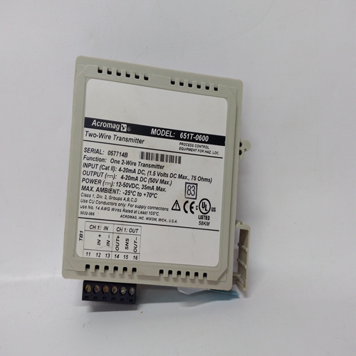
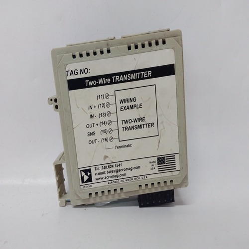
ACROMAG 651T-0600控制设备
通信部分。“LOOP#”和“LIL CHAN”参数允许配置循环索引
Modbus数据的编号(x)或LIL回路数据的起始信道(n)。
输入CL控制对来自网络的环路数据的更改的本地仲裁。当未配置输入CL时三个状态输出LO(在1.21固件中,此输出命名为L)、CN和CM将设置为高(1)并更改可以通过网络命令或本地面板进行。配置CL时,可以在本地进行更改从按钮开关,如PB1SW输出PS(配置为瞬时),并将从本地变为控制台或控制台/计算机到本地,输入的每个正向转换。当输出LO变高时,输出CN也将变高,CM将变低,表明控制源将变为控制台
无论何时通过输入CL上的正转换或从网络命令禁用本地。计算机可以使用网络命令将CM状态设置为高。NL输出通常连接到的MD输入按钮块PB1SW用于指示操作员面板上的C/L开关位置,C为绿色LED,红色为红色
LO的LED。当控制器未能在看门狗内接收到Modbus网络命令时,输出WD将变高(1)
时间看门狗时间在STATN(站参数)功能块中设置
。输入A可用于:确认控制器中所有回路中的所有报警。输出PN(脉冲开启)将变高0.5秒(或一个扫描周期,以较长者为准)。条形图闪烁由优先级控制
报警或事件的设置。闪烁条形图停止时,输出PF(脉冲关闭)将变高0.5秒(例如,按下确认按钮)。奇数功能块是五个操作员显示器之一,其:可在每个循环一次的基础上用于配置本地操作员显示功能以及网络参数。请参阅下一页的i|ware PC面板示例。奇数功能块最多显示16个离散变量。每个输入具有相应的块输出,该块输出:等于变量模式为自动时的输入。每个输入变量可以分配一个模式。价值在人身上,可以使用脉冲发生器改变输出并按下确认按钮。切换变量时对于手动,它将始终等于输入值,直到更改。LOOP#参数用于索引对的读写Modbus和LIL网络参数。当使用LIL时,还必须配置LIL CHAN参数。看见有关网络参数的更多信息,请参见第6节。视图OD参数设置为“是”时,启用操作员显示可在本地查看和访问。在案例中其中需要查看显示或操作参数仅来自网络工作站,参数应为设置为NO。
Communications’ section. The ‘LOOP #’ and ‘LIL CHAN’ parameters enable configuration of a loop index
number (x) for Modbus data or a starting channel (n) for LIL loop data.
Input CL controls local arbitration of changes to loop data from the network. When input CL is not configured, the
three status outputs LO (in 1.21 firmware this output was named L), CN, and CM will be set high (1) and changes
can be made from a network command or the local faceplate. When CL is configured, it can be changed locally
from a pushbutton switch such as PB1SW output PS (configured as momentary) and will change from local to
console or console/computer to local with each positive transition of the input. Also, when output LO goes high,
output CN will also go high and CM will go low, indicating that the control source will change to Console
whenever Local is disabled, either by a positive transition on input CL or from a network command. The Computer
CM state can be set high using a network command. The NL output will normally be connected to the MD input of
pushbutton block PB1SW to indicate the C/L switch position on the operator faceplate, a green LED for C and a red
LED for LO.
Output WD will go high (1) when the controller fails to receive a Modbus network command within the watchdog
time. The watchdog time is set in the STATN (Station Parameters) function block. Input A can be used to
acknowledge all the alarms in all of the loops in a controller. Output PN (Pulse oN) will go high for 0.5 seconds (or
one scan cycle whichever is longer) whenever the bargraph flashes. Bargraph flashing is controlled by the priority
setting of alarms or events. Output PF (Pulse ofF) will go high for 0.5 sec when the flashing bargraph is stopped
(e.g. pressing the ACK button). ODD function blocks are one of five operator displays that
can be used on a one per loop basis to configure the local
operator display functions as well as network parameters.
See the i|ware PC faceplate example on the next page.
The ODD function block displays up to 16 discrete
variables. Each input has a corresponding block output that
is equal to the input when the variable mode is in Auto.
Each input variable can be assigned a mode. The value of
the output can be changed while in Man by using the pulser
and pressing the ACK button. When a variable is switched
to Manual it will always equal the input value until changed.
The LOOP # parameter is used to index reads and writes to
Modbus and LIL network parameters. When using the LIL,
the LIL CHAN parameter must also be configured. See
Section 6 for more information on network parameters.
The VIEW OD parameter, when set to YES enables the
operator display to be viewed and accessed locally. In cases
where it is desired to view display or operation parameters
only from a network workstation, the parameter should be
set to NO.

