


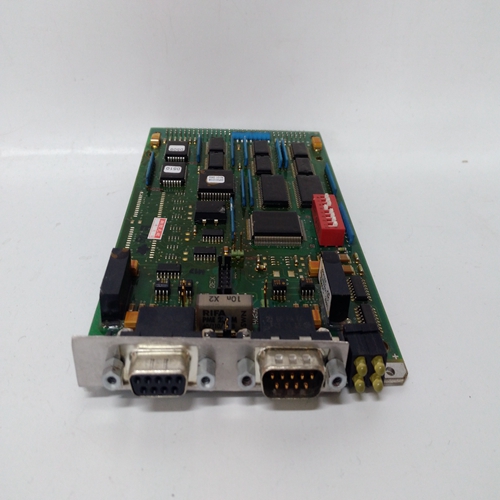

3EGM030300R0002脉冲输入卡件
ODC块是上使用的五个操作员显示器之一每个循环一个,用于配置本地操作员显示来自远程操作员的功能和网络参数与回路相关的工作站。查看i|ware PC下一页的面板。
固件1.30及更高版本中包含以下功能。1.一个新参数,视图OD,当设置为是时默认设置,允许查看操作员显示并使用循环按钮本地访问。在某些情况下在这种情况下,可能需要仅查看显示或操作网络工作站的参数,不允许从本地操作或查看控制回路陈列此处,参数应设置为“否”。
2.当循环事件激活时,输出LE为高(1)。输出当站错误激活时,SE为高。
3.循环#(此参数为版本中的MB索引1.21)用于索引对Modbus的读取和写入参数。LIL具有25个参数:C1S、C2S、C3S,..C25S。选择ODC块后,以及循环#已配置,相应的C#LIL参数将包含LIL起始通道(n)地方必须输入循环#才能启用LIL或Modbus通信。
过程/设定点和阀门的范围指针必须配置条形图以定义P、S和V的变量输入。如果这些参数不是配置后,将使用工程图缩放条形图范围为0.00到100.00。X和Y的范围指针定义显示的小数点位置和单位代码。
该信息还定义了循环的缩放通过提供给远程工作站的信息网络(即Modbus或LIL)。
输入变量P、S、V、X和Y显示在数字显示中,使用工程单位和首选范围指针的DPP。在BATOT内配置时,也将显示BATOT的总计块如果值大于DPP参数允许的值,小数点将移动以允许显示
显示完整数字,直到超过最大可用数字,此时将指示超出范围。
当输入U1或U2变为高(1)时,8字符的用户状态(U_status)将显示为状态优先级(U_优先)。优先级为0将禁用该状态功能,将状态字中的位设置为0。
有关使用优先级1至5的显示动作的说明,请参见第9节“操作”。
水平条形图可以选择为直接作用或反向作用。此功能允许它始终指示完全点亮时打开阀门。基本面板上的标签是固定的,但粘贴标签可用于更改适应症。V NET AC参数允许为直接或反向动作设置LxVI网络参数。
这使得HMI上的阀杆能够与面板上的阀条类似地操作。左栏和右栏应相应设置标签(例如,左=打开,右=关闭)。操作员显示器必须配置为将控制器回路数据映射到网络数据。环路网络数据已映射
当使用标准Modbus接口时,进入寄存器或线圈,当可选LIL时,进入通道/参数已添加接口。Modbus和LIL的映射列于“网络”中的表格中
ODC blocks are one of five operator displays that are used on a one per loop basis to configure the local operator display functions and network parameters from a remote operator workstation associated with the loop. See the i|ware PC faceplate on the next page. The following features are in firmware 1.30 and higher. 1. A new parameter, VIEW OD, when set to YES, the default setting, enables the operator display to be viewed and accessed locally using the LOOP button. In some cases, it may be desired to view only display or operation parameters with a network workstation and not allow operation or viewing of the control loop from the local display. Here the parameter should be set to NO. 2. Output LE is high (1) when a loop event is active. Output SE is high when a station error is active. 3. The LOOP # (this parameter was MB INDEX in version 1.21) is used to index reads and writes to Modbus parameters. The LIL has 25 parameters: C1S, C2S, C3S, ..... C25S. When an ODC block has been selected and the LOOP # has been configured, the corresponding C#S LIL parameter will contain the LIL starting Chan (n) location. The LOOP# must be entered to enable either LIL or Modbus communications. Range pointers for both the process/setpoint and valve bargraphs must be configured to define the range of the variable inputs to P, S, and V. If these parameters are not configured, the bargraphs will be scaled using the engineering range of 0.00 to 100.00. The range pointer for X and Y define the displayed decimal point position and the units code. This information also defines the scaling of the loop information provided to a remote workstation over the network (i.e. Modbus or LIL). Input variables P, S, V, X, and Y are shown in the numeric display, using the engineering UNITS and the preferred DPP of the range pointer. The Total from the BATOT will also be displayed when configured within the BATOT block. If a value is greater than allowed by the DPP parameter, the decimal point will be shifted to allow the display to show the full number, until it exceeds the maximum available digits, at which time it will indicate over range. When input U1 or U2 goes high (1), the 8-character user status (U_STATUS) will be displayed as configured by the status priority (U_ PRIOR). A priority of 0 will disable that status function setting the bits in the status word to 0. See Section 9 Operation for a description of display actions using priorities 1 to 5. The horizontal bargraph can be selected as direct or reverse acting. This feature allows it to always indicate an OPEN valve when fully lit. The labels on the basic faceplate are fixed, but paste on labels can be used to change the indications. The V NET AC parameter allows the LxVI network parameter to be set for direct or reverse action. This enables the valve bar on the HMI to operate similar to the valve bar on the faceplate. The left and right bar labels should be set accordingly (e.g. Left = “OPEN & Right = CLOSE). An operator display must be configured to map controller loop data to network data. Loop network data is mapped into registers or coils when the standard Modbus interface is used and to channels/parameters when the optional LIL interface has been added. Mappings for both Modbus and LIL are listed in the tables included in the ‘Network

