


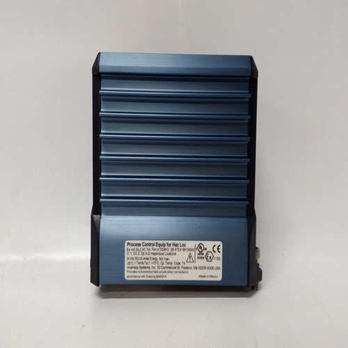

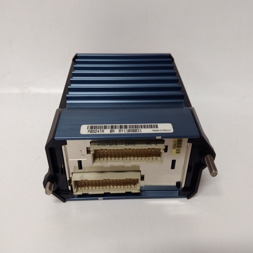

P0924TR输入输出模块
TO(跟踪输出)通常用于使用外部设备设置偏置的应用中偏置参数的位置(然后将B设置为0.0)。当需要使偏置块的输出跟踪TV变量,外部设备被迫跟踪。输入E将等于TV-[A+(0.0)],因此块输出O1的偏置将等于TV。在i|config中编辑包含偏置功能块的配置,然后将其下载到在线控制器将忽略偏置参数值的变化,并继续以预降负荷值运行。3.2.25 CIE_线圈输入-以太网(V3.0)CIE_功能块在以下情况下可用:
可选以太网通信板8是安装在控制器中。它启用控制器从其他站点获取线圈数据以太网。
最多可提供32个CIE_块。积木是按顺序分配,控制器范围,每个使用最多可从以下位置获得16个线圈:Modbus设备。每个线圈分配给块输出C0–CF。
IP地址参数用于配置源Modbus设备的IP地址。
这个MB ADRES参数允许Modbus地址待配置。
当连接到其他西门子摩尔控制器,Modbus地址设置为1。在某些情况下,其他Modbus设备可能使用不同的地址,或者通过Modbus TCP/IP网关,Modbus网络可能有多个设备,每个设备具有唯一的住址
START CL参数标识第一个线圈的位置。后续线圈(最多16个)可通过以下方式获得:将CL参数的编号设置为大于1的值。数据类型参数启用线圈读数(Modbus功能代码01)或输入(Modbus功能码02)。两者处理相同,但线圈类型为:最常见的用法。UD速率参数配置块请求数据的速率。这个P2P设置将以以太网块中P2P速率参数设置的速率更新数据。Ct设置将在控制器的循环时间更新数据。
输出QS指示接收数据的质量,当数据不好时,输出QS将变高(1)。这通常是与由于通信故障或源的错误配置而无法接收数据相关。
CHR_功能块提供10个段,可以:用于表征X输入信号。个人通过输入Xn、Yn和Xn+1来配置段,每个段的Yn+1点。所有Xn+1点必须为大于相关的Xn点。输入X在工程单位和Y点应在表征器输出所需的工程单位。
The TO (Tracked Output) is normally used in applications where an external device is being used to set a bias in
place of the BIAS parameter (B is then set to 0.0). When it is desired to have the output of the BIAS block track the
TV variable, the external device is forced to track TO. Input E will then equal TV- [A+(0.0)] and, therefore, the
BIAS block output O1 will equal TV.
When a configuration containing the BIAS function block is edited in i|config and then downloaded to an on-line
controller, the controller will ignore a change to the BIAS parameter value and continue to run with the predownload value. 3.2.25 CIE_- Coil Inputs - Ethernet (V3.0)
CIE_ function blocks are available when the
optional Ethernet communication board8
is
installed in the controller. It enables the controller
to obtain Coil data from other stations over the
Ethernet network.
Up to 32 CIE_ blocks are available. Blocks are
assigned in sequence, controller wide, with each
use. Up to 16 Coils can be obtained from a
Modbus device. Each Coil is assigned to block
outputs C0 – CF.
The IP ADRES parameter is used to configure the
IP address of the source Modbus device. The
MB ADRES parameter allows a Modbus address
to be configured. When connecting to other
Siemens MOORE controllers, the Modbus
address is set to 1. In some cases, other Modbus
devices may use a different address or when
going through a Modbus TCP/IP gateway a Modbus network may have multiple devices, each having a unique
address.
The START CL parameter identifies the location of the first Coil. Subsequent Coils, up to 16, can be obtained by
setting the NO OF CL parameter to a value greater than 1. The DATA TYP parameter enables reading of Coils
(Modbus Function Code 01) or Inputs (Modbus Function Code 02). Both are treated the same but the Coil type is
the most common usage. The UD RATE parameter configures the rate at which the block will request data. The
P2P setting will update the data at the rate set by the P2P RATE parameter in the ETHERNET block. The Ct
setting will update the data at the cycle time of the controller.
Output QS indicates the quality of the received data and will go high (1) when the data is bad. This is normally
associated with failure to receive data due to a communication failure or a misconfiguration of the source.
CHR_ function blocks provide 10 segments that can be
used to characterize the X input signal. Individual
segments are configured by entering the Xn, Yn and Xn+1,
Yn+1 points for each segment. All Xn+1 points must be
greater than the associated Xn points. Input X is in
engineering units and the Y points should be in the
engineering units desired for the characterizer output.

