


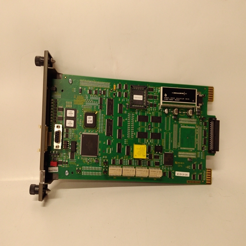

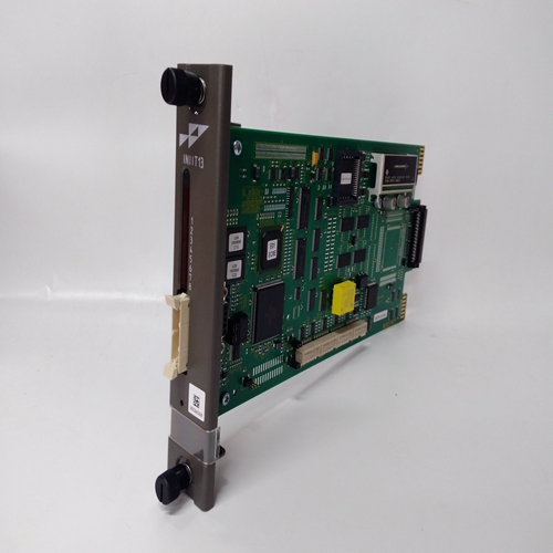
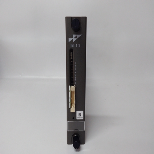
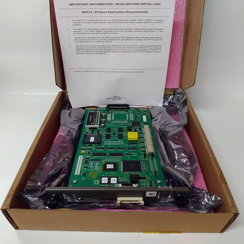
INIIT13输入卡件
将上次校准日期设置为当前日期,并重置校准提醒(如果启用)。
c、 自动返回到正常的选定状态,但是控制卡上的抑制将保持激活状态。
d、 如果显示值超出存储的信号限制,则显示错误消息。
e、 在配置用于催化传感器输入的控制卡上
当传感器是新的。如果灵敏度传感器已降至其原始值的50%以下。
重要的当量距气已移除且传感器信号已
恢复正常,不要忘记将控制卡恢复到其未受限制状态状态第一时间跨度信号校准
当按下第1个量程按钮时,所选的控制卡与按下SPAN按钮时类似。
要执行第一次时间跨度校准,请按中所示进行第9节步骤(1)至(6),但按下第1档按钮。
注:1.在步骤(6)中,当量程校准更新时,新的传感器校准日期和上次传感器校准日期都将设置为当前日期。2.在配置用于催化传感器输入的控制卡上传感器量程信号值记录为新传感器
价值该值将用于提供传感器寿命监测将数据与以下过程中获得的后续值进行比较:
随后使用量程按钮进行校准。传感器信号监测
信号按钮的操作允许监控
所选通道传感器信号值。显示的参数为:取决于安装到所选的传感器驱动模块的类型频道卡。
要进入传感器信号监控操作,请按以下步骤进行:
(1) 按住所需的通道卡复位/选择按钮约1.5秒,直到出现所选图标在频道显示器上。
(2) 按下信号按钮,所选频道卡显示将指示传感器信号。显示的值将取决于
安装在通道卡上的传感器驱动模块类型如下:a、 催化传感器驱动模块显示器将显示带电电桥电压在01和02之间测量,单位为mV。02是惠斯通下半部分的中心点通道卡上的桥。
b、 4-20mA传感器驱动模块显示器将显示带电传感器回路电流在马。
(3) 上述读数不可更改按下或按钮将:将所选控制卡返回到所选模式。
Set the last calibration date to the current date and reset the
calibration reminder if this is enabled.
c. Automatically return to the normal selected state, however, the
inhibit on the control card will remain active.
d. If the displayed value is outside the stored signal limits, display
an error message.
e. On control cards configured for catalytic sensor inputs, the present
sensor signal will be compared with that recorded when the
sensor was new. A warning will be displayed if the sensitivity of
the sensor has fallen to below 50% of its original value.
IMPORTANT
When the span gas has been removed and the sensor signal has
returned to normal, do not forget to return the control card to its uninhibited
state.FIRST TIME SPAN SIGNAL CALIBRATION
When the 1st SPAN push-button is pressed, the operation of the selected
control card is similar to when the SPAN push-button is pressed.
To carry out the first time span calibration, proceed as indicated in
Section 9 Steps (1) to (6) but push the 1st SPAN push-button.
Note: 1. In Step (6) when the span calibration is updated, the new
sensor calibration date and the last sensor calibration date
will both be set to the current date.
2. On control cards configured for catalytic sensor inputs, the
sensor span signal value is recorded as the new sensor
value. This value will be used to provide sensor life monitoring
data by comparison with subsequent values obtained during
later calibrations using the SPAN button.SENSOR SIGNAL MONITORING
The operation of the SIGNAL push-button allows the monitoring of the
selected channels sensor signal value. The displayed parameter is
dependent upon the type of sensor drive module fitted to the selected
channel card.
To enter the sensor signal monitoring operation, proceed as follows:
(1) Push and hold the required channel card RESET/SELECT pushbutton for approximately 1.5 seconds until the selected icon appears
on the channel display.
(2) Push the SIGNAL push-button and the selected channel card display
will indicate the sensor signal. The displayed value will depend on the
type of sensor drive module fitted to the channel card as follows:
a. Catalytic Sensor Drive Module
The display will show the live bridge voltage
measured between 01 and 02 in mV. 02 is the
centre point of the second half of the Wheatstone
bridge which is on the channel card.
b. 4 - 20mA Sensor Drive Module
The display will show the live sensor loop current
in mA.
(3) No alterations can be made to the above readings
and pressing either the or push-buttons will
return the selected control card to the selected mode.

