


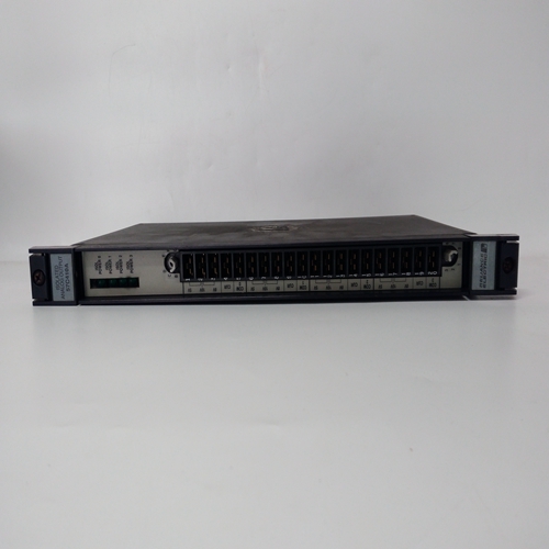

RELIANCE 57C410A模块
报警配置和继电器测试
报警配置和继电器测试操作循环8次
不同阶段,A1、A2、A3、STEL、LTEL、TESTAI、A2.A3、TESTEL和TESTLTEL。在前三个阶段中,报警LED和继电器不会:
有效。前五个阶段用于设置报警阈值点
而最后三个阶段提供灯测试和继电器测试功能。
要选择报警配置操作,请执行以下操作:
(1) 将工程钥匙插入工程卡前面板插座并检查解锁的LED()是否点亮。
(2) 按住所需的控制卡复位/选择按钮约1.5秒,并检查所选
控制卡通过显示select(选择)来表示已选择偶像
(3) 按下工程卡报警按钮,并检查
所选控制卡信息显示显示上升报警的A1阈值或A1表示下降报警阈值。
(4) 检查所选控制卡数字显示屏是否指示A1报警阈值点。
模拟显示器继续显示传感器的活动状态测量
2.如果报警被禁用,数字屏幕上将显示“--”显示,无法进行调整。
(5) 如果需要,使用和按钮设置新的A1报警阈值点。
注意:阈值级别只能设置为介于控制卡配置中设置的高点和低点。
(6) 当设置了正确的液位时,如果不再进行调整需要时,按下按钮设置新级别并存储永久地否则进入步骤(7)。注:如果需要随时取消程序而不更改原始设置为显示值,按下按钮。
(7) 再次按下工程卡报警按钮,并重复步骤(4)至(6)进行A2阈值设置。
(8) 第三次按下工程卡报警按钮,然后对A3阈值点设置重复步骤(4)至(6)。
(9) 第四次按下工程卡报警按钮,然后对STEL阈值点设置重复步骤(4)至(6)。
(10) 第五次按下工程卡报警按钮,然后对LTEL阈值点设置重复步骤(4)至(6)。
ALARM CONFIGURATION AND RELAY TEST
The alarm configuration and relay test operation cycles through eight
different stages, A1, A2, A3, STEL, LTEL, TESTAI, A2. A3, TESTSTEL and
TESTLTEL. In the first three stages the alarm LEDs and relays are not
effected. The first five stages are used to set the alarm threshold points
while the last three stages provide a lamp test and relay test function.
To select the alarm configuration operation, proceed as follows:
(1) Plug the Engineering Key into the Engineering Card front panel
socket and check that the Unlocked LED ( ) is illuminated.
(2) Push and hold the required control card RESET/SELECT pushbutton for approximately 1.5 seconds and check that the selected
control card indicates it has been selected by displaying the select
icon.
(3) Push the Engineering Card ALARMS push-button and check that the
selected control card message display shows A1 for a rising alarm
threshold or A1 for a falling alarm threshold.
(4) Check that the selected control card digital display indicates the A1
alarm threshold point.
Notes: 1. The analogue display continues to show the sensor live
measurement.
2. If an alarm is disabled, '- - - -' will be shown on the digital
display and no adjustment will be possible.
(5) If required, use the and push-buttons to set a new A1 alarm
threshold point.
Note: The threshold level can only be set to a level that is between the
high and low points set in the Control Card configuration.
(6) When the correct level has been set, and if no more adjustments are
required, push the push-button to set the new level and store this
permanently. Otherwise proceed to Step (7).
Note: If it is required to cancel the procedure at any time without altering
the original setting to the displayed value, press the push button.
(7) Push the Engineering Card ALARMS push-button a second time and repeat Steps (4) to (6) for the A2 threshold points setting.
(8) Push the Engineering Card ALARMS push-button a third time and
repeat Steps (4) to (6) for the A3 threshold points setting.
(9) Push the Engineering Card ALARMS push-button a fourth time and
repeat Steps (4) to (6) for the STEL threshold points setting.
(10) Push the Engineering Card ALARMS push-button a fifth time and
repeat Steps (4) to (6) for the LTEL threshold points setting.

