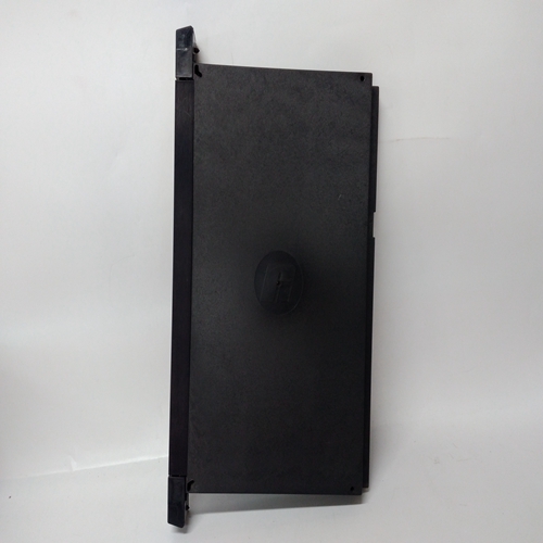
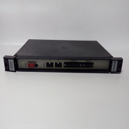
57C404C工控模块
按下时钟按钮,选择信道卡显示将指示当前时间。
注:时钟采用24小时格式。
(3) 再次按下时钟按钮,然后所选频道卡显示将指示当前日、月和年。
注:1.日和月的显示格式可为DD.MM或MM.DD,取决于系统的配置。
2.进一步按下时钟按钮将在时间和日期之间切换显示。
(4) 按下()或()按钮或等待30秒退出时钟模式。
4.8维护记录打印输出每个通道状态的详细打印输出或可以使用工程卡启动整个机架。数据被馈送以ASCII文本格式发送到工程上的工程串行端口卡在前面板上。
要输出每个通道卡的维护记录,请按跟随:
(1) 将RS232打印机插入工程卡串行端口。
(2) 按住所需的通道卡复位/选择按钮按钮约1.5秒,直到出现所选图标在频道显示器上。
(3) 同时按下向上()和向下()按钮。选定的通道卡将显示PRN,同时输出以下数据:要输出整个机架的摘要,请按以下步骤进行:
(1) 将RS232打印机插入工程卡串行端口。
(2) 同时按下向上()和向下()按钮,不使用任何按钮
正在选择通道卡,并将打印以下数据:
工程师的操作说明涉及附加设施
可用于设置和维护系统。因为系统可能会被这些功能改变或阻碍,它们只能当工程人员解锁工程卡时执行
钥匙工程操作程序
根据操作的键盘功能按钮
可执行以下工程操作程序:信道复位。频道选择。
通道抑制。报警配置和继电器测试。
催化桥电流调节。
零信号校准。
量程信号校准。
第一量程信号校准。
传感器信号监控。时钟/日历调整。
通道选择和复位由通道卡复位执行/选择按钮。见第6章第3节。
其余工程功能在控制卡之后执行已使用工程卡按钮控件选择。
Push the CLOCK push-button and the selected
channel card display will indicate the present time.
Note: The clock uses the 24 hour format.
(3) Push the CLOCK push-button a second time and the
selected channel card display will indicate the present
day, month and year.
Notes: 1. The display format for day and month can read
either DD.MM or MM.DD depending on the
configuration of the system.
2. Further pushes of the CLOCK push-button will
toggle the display between time and date.
(4) Push the ( ) or ( ) push-buttons or wait 30 seconds to exit the
CLOCK mode.
4.8 Maintenance Record Print Out
A detailed printout of the status for each channel or a summary of the
whole rack can be initiated using the Engineering Card. The data is fed
in ASCII text format to the engineering serial port on the Engineering
Card front panel.
To output the maintenance record for each channel card, proceed as
follows:
(1) Plug a RS232 printer into the Engineering card serial port.
(2) Push and hold the required channel card RESET/SELECT push
button for approximately 1.5 seconds until the selected icon appears
on the channel display.
(3) Push the up ( ) and down ( ) buttons simultaneously. The selected
channel card will display PRN while outputting the following data:To output a summary of the whole rack, proceed as follows:
(1) Plug a RS232 printer into the Engineering Card serial port.
(2) Push the up ( ) and down ( ) buttons simultaneously without any
channel card being selected and the following data will be printed:
The engineer's operating instructions refer to the additional facilities
available to setup and maintain the system. Because the operation of the
system can be altered or impeded by these functions, they can only be
performed when the Engineering Card is unlocked by the Engineering
Key. ENGINEERING OPERATING ROUTINES
Depending upon the which keypad function push-button is operated, the
following engineering operating routines may be carried out:
Channel Reset.
Channel Select.
Channel Inhibit.
Alarm Configuration and Relay Test.
Catalytic Bridge Current Adjustment.
Zero Signal Calibration.
Span Signal Calibration.
1st Span Signal Calibration.
Sensor Signal Monitoring.
Clock/Calendar Adjustment.
Channel select and reset are carried out by the channel card RESET/
SELECT push-button. See Chapter 6, Section 3.
The remaining engineering functions are carried out after a control card
has been selected using the Engineering Card push-button controls.


