


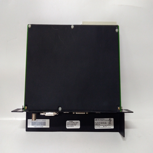
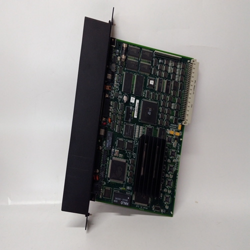

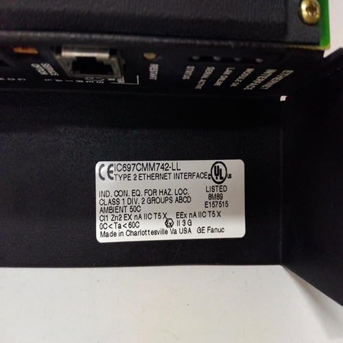
IC697CMM742通用电气卡件
检查第节中的错误代码表5用于解释。
检查消息显示是否存在错误代码。参见第5节错误代码的解释。
检查传感器连接和活动至少等待255秒,看看是否LED熄灭。
将工程师钥匙插入工程卡,然后操作禁止按钮。这应该是打开和关闭禁止LED,否则,检查远程抑制数量
从中取出工程钥匙工程卡。检查所有控制卡是否正确安装在机架上并正在工作。
如果卡已被移除故意,符合工程关键进入工程卡插座,并然后再次取出钥匙。
依次选择每个控制卡,使用其中一张工程卡功能,检查通信存在于所选控制卡之间和工程卡。
检查直流电源是否更多大于16V
暂时按下复位/选择按钮以移除锁定报警状态。报警指示灯为:照明,但没有继电器操作。
故障指示灯为:照明,但没有继电器操作。
禁止LED为:照明,但没有继电器操作。
符号显示在消息显示。XXXX显示在当工程功能具有:被选中。
工程卡按钮无效。检查频道是否在抑制条件,如有必要移除抑制。
检查继电器的类型安装的接口卡可以支持预期警报。
检查通道卡配置查看继电器是否配置为:预期的操作。
将继电器接口卡与另一个相同类型和测试继电器使用工程卡采取的措施报警测试功能。
请参阅前面的报警LED指南。
工程卡没有工程钥匙装上了。
如果安装了钥匙,但未锁定()LED未点亮。检查以下情况:工程键和替换
必需的所选功能不可用在存在的信道硬件上。
选择频道卡。检查工程卡电源on()LED点亮。
Check the error code tables in Section
5 for explanation.
Check the message display for an
error code. See Section 5 for
explanation of error codes.
Check sensor connection and
operation.
Wait for at least 255 seconds to see if
the LED extinguishes.
Insert the Engineers Key into the
Engineering Card and then operate
the INHIBIT push-button. This should
toggle the inhibit LED on and off,
otherwise check the remote inhibit
level.
Remove the Engineering Key from the
Engineering Card.
Check that all the control cards are
fitted to the rack and are working.
If a card has been removed
deliberately, fit the Engineering Key
into the Engineering Card socket and
then remove the key again.
Select each control card in turn and,
using one of the Engineering Card
functions, check that com-munications
exist between the selected control card
and Engineering Card.
Check that the dc power supply is more
than 16V.
Press the RESET/SELECT pushbutton momentarily to remove the
latched alarm condition.The ALARM LED is
illuminated but there is no
relay operation.
The FAULT LED is
illuminated but there is no
relay operation.
The INHIBIT LED is
illuminated but there is no
relay operation.
symbol showing on the
message display.
XXXX is displayed on the
message display when an
engineering function has
been selected.
The Engineering Card pushbuttons have no effect.
Check to see if the channel is in the
inhibited condition and if necessary
remove the inhibit.
Check to see that the type of relay
interface card fitted can support the
expected alarm.
Check the channel card configuration
to see that the relay is configured for
the expected operation.
Swop the relay interface card with
another of the same type and test relay
action by using the Engineering Card
alarm test function.
See previous guide for ALARM LED.
See previous guide for Alarm LED.
Engineering Card has no Engineering
Key fitted.
If key is fitted but the unlocked ( ) LED
is not illuminated check the condition of
Engineering Key and replace if
necessary.
The function selected is not available
on the channel hardware present.
Select a channel card.
Check that the Engineering Card power
on ( ) LED is illuminated.

