


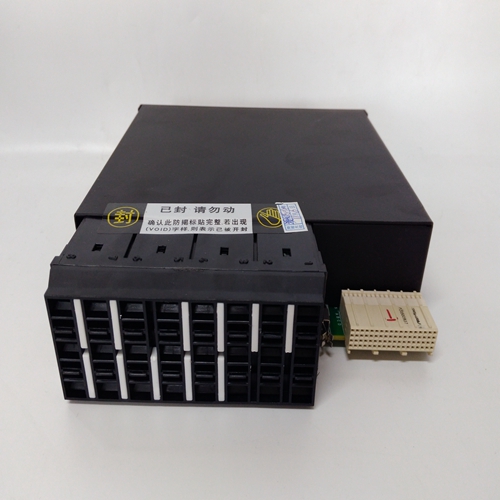
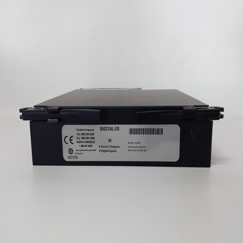
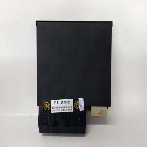
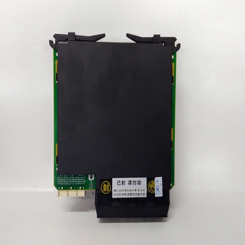
UR6EV综合保护继电模块
启动程序在此之前,应详细检查系统接线启动程序。
按如下方式启动系统:
(1) 确保系统电源已关闭。
(2) 通过以下方式断开与直流输入卡的电源连接:拆下两件式连接器TB1。拆下接线盒TB2如果使用的话。
(3) 拧下用于固定控制卡的两个固定螺钉然后,使用提取工具,从使机架之间没有电气连接控制卡和背板。
4) 打开系统电源。
(5) 检查是否存在18V和32V直流电压之间的电压接线盒TB1。通过检查
催化传感器的磁珠mA和mV信号或mA信号
对于4-20mA传感器。
(15) 对中的其余控制卡重复步骤(11)至(14)支架
(16) 将接线盒TB2重新连接到直流输入卡,并测试可选工程卡模块,符合相关操作手册说明。
(17) 使用继电器测试验证每个通道的报警配置第7章第6节概述的程序。
(18) 验证系统57控制卡和电源是否正常在最高规定工作温度下工作温度为55℃。
校准让连接的传感器稳定一段适当的时间,如下所示:传感器手册中规定。
调整催化传感器的传感器头电流,如中所述第7章第7节至传感器中指示的所需值操作说明。
使用所用传感器类型的程序,遵循第7章第8节和第10节中的零量程和第一量程操作指南,并校准每个通道。
维护为确保系统正常运行,应进行以下维护:根据现场规定定期进行,以及所用传感器类型的说明。对于安装在应遵循欧盟EN 50073。
START UP PROCEDURE
A detailed check of the system wiring should be carried out prior to this
start-up procedure.
Start-up the system as follows:
(1) Ensure that the system power supply is switched off.
(2) Disconnect the power supply connections to the DC Input Card by
removing the two part connector TB1. Remove terminal block TB2
if used.
(3) Unscrew the two retaining screws used to secure the control cards
and then, using the extraction tool, partially remove the cards from
the rack so that there is no electrical connection between the
control cards and the backplane.
(4) Switch on the system power supply.
(5) Check that a voltage of between 18V and 32V dc exists at the
terminal block TB1.
Check the operation of the connected sensor by checking the
BEAD mA and mV SIGNAL for a catalytic sensor or the mA SIGNAL
for a 4 - 20mA sensor.
(15) Repeat Steps (11) to (14) for the remaining control cards in the
rack.
(16) Reconnect the terminal block TB2 to the DC Input Card and test the
optional Engineering Card module in accordance with the relevant
operating manual instructions.
(17) Verify the alarm configuration for each channel using the relay test
procedure outlined in Chapter 7 Section 6.
(18) Verify that the System 57 Control Cards and power supply are
operating within the maximum specified operating temperature
of 55 C.
CALIBRATION
Leave the connected sensors to stabilise for a suitable period as
specified in the sensor manual.
Adjust the sensor head current of catalytic sensors as described in
Chapter 7 Section 7 to the required value as indicated in the sensor
operating instructions.
Using the procedures for the type of sensors being used, follow the
zero and 1st span operational guide in Chapter 7 Sections 8 and 10,
and calibrate each channel.
MAINTENANCE
To ensure that the system functions correctly, maintenance should be
carried out on a regular basis as dictated by the site regulations and
instructions for the type of sensor being used. For installations in the
EU, EN 50073 should be followed.

