


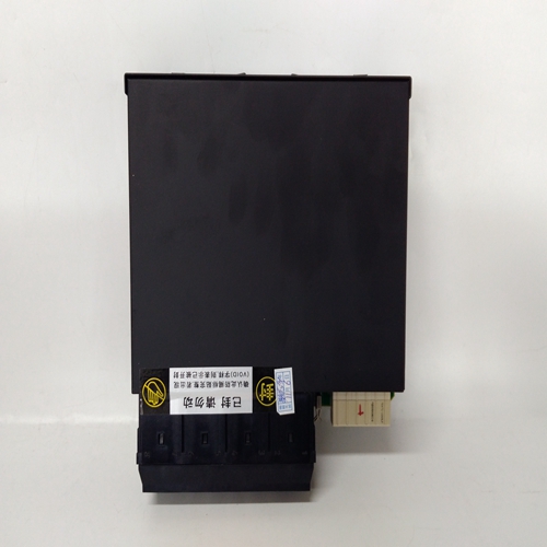
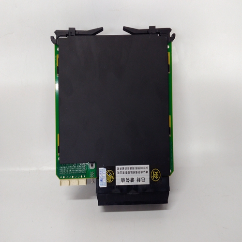

UR6AV综合保护继电器
将16路交流至直流电源装置升级至150W,或200W进行如下操作:
(1) 安装第二个50W子单元,包含50W切换模式模块,连接至16路交流至直流电源装置前面板使用提供的固定件。
(2) 当需要升级到200W时,再安装一个50W开关如第17.2节所示,将模式模块插入新的50W子单元。
警告系统电源处可能存在高交流电源电压单元和接口卡的继电器端子。适当的调试或维修时必须采取安全预防措施系统。
重要的应进行系统的调试和维护仅由经过培训的授权人员执行。
1.概述
以下调试和维护指南应:与发布的相关说明一起使用正在使用传感器。
以下信息适用于使用单个直流输入卡的电源连接。有关
每个单独通道通电的系统,请联系Zellweger Analytics。
(6) 关闭电源。
(7) 将接线盒TB1重新连接至直流输入卡。
(8) 打开系统电源。
(9) 检查是否仍存在18V和32V直流电压之间的电压接线盒TB1。
(10) 检查工程卡前面板上的电源()是否为绿色LED点亮,解锁()LED闪烁。
(11) 将插槽1中的控制卡完全推入机架,使其与背板连接,并用两个固定件固定螺钉。
(12) 检查显示器是否工作,以及控制卡前面板点亮。
(13) 检查在预定义的启动禁止期后,通常为30秒,禁止LED熄灭。
To upgrade the 16-Way AC to DC Power Supply Unit to 150W or
200W proceed as follows:
(1) Fit a second 50W Sub unit, containing a 50W Switched Mode
Module, to the 16-way AC to DC Power Supply Unit front panel
using the fixings supplied.
(2) When an upgrade to 200W is required, fit a further 50W Switched
Mode Module into the new 50W Sub unit as indicated in Section 17.2.
WARNING
High ac mains voltages may be present at the system power supply
unit and at the relay terminals of the interface cards. Appropriate
safety precautions must be taken when commissioning or servicing
the system.
IMPORTANT
Commissioning and maintenance of the system should be carried out
by trained authorised personnel only.
1. GENERAL
The following guide to commissioning and maintenance should be
used in conjunction with the relevant instructions issued with the
sensors being used.
The following information applies to the setup of a system with a single
power supply connection to the DC Input Card. For information on
systems where power is applied to each individual channel, please
contact Zellweger Analytics.
(6) Switch off the power supply.
(7) Reconnect the terminal block TB1 to the DC Input Card.
(8) Switch on the system power supply.
(9) Check that a voltage of between 18V and 32V dc still exists at the
terminal block TB1.
(10) Check that the Engineering Card front panel power on ( ) green
LED is illuminated and the unlocked ( ) LED is flashing.
(11) Push the control card in slot 1 fully into the rack so that it makes
connection with the backplane and secure with the two securing
screws.
(12) Check that the display operates and that the INHIBIT LED on the
control card front panel is illuminated.
(13) Check that after the pre-defined start up inhibit period, typically 30
seconds, the INHIBIT LED is extinguished.

