


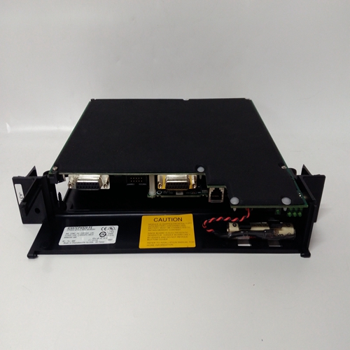
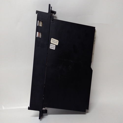
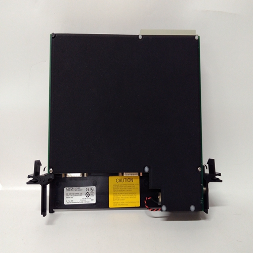
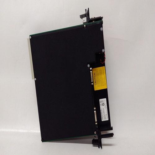
IC697CPX928燃机卡件
如果传感器局部接地,则:接地螺柱或穿过传感器外壳或安装,以避免屏幕接地回路
电缆护套只能连接在一端,即在传感器处或在接口/中继卡。4-20mA回路供电传感器连接
回路供电传感器需要双线连接,且传感器文档将指示正回路连接和负回路连接,通常分别为棕色和蓝色。
在现场电缆的系统57端,两条传感器导线应:每个都连接到上的S、01或NS端子之一
连接到所需单体的现场接口或中继卡频道显示卡。所使用的两个端子将根据不同而不同取决于测量电阻的位置是否在回路中供应或返回路径。还必须在4上正确设置链接选项
-20mA传感器驱动模块(见第12.3节)。
传感器电缆屏蔽应连接至系统接地。
这可以在现场接口/中继卡上使用接地端子或电缆使用金属进入机柜的位置或通过其它合适的方式。注:如果传感器局部接地,则接地螺柱或通过传感器外壳或安装,以避免接地回路
电缆的屏蔽护套应仅在一端连接,i、 例如在传感器处或在接口/中继卡处。如果传感器局部接地,则接地螺柱或通过传感器外壳或安装,以避免接地回路电缆的屏蔽护套应仅在一端连接,
i、 例如在传感器处或在接口/中继卡处。
4-20mA变送器连接
注意安全导出单通道控制卡提供的功率从直流输入到系统57(18V到32V)。检查待连接的变送器与实际电源兼容使用的电压。来自现场终端的最大电流为现场供电的单个单通道控制卡
装置为500mA,但是,来自所有通道不应超过最大背板负载电流8A。
由单通道控制卡供电的变送器需要:三线或四线连接以及传感器文档将指示0V和+24V电源连接以及正极和
负回路连接。在现场电缆的系统57端,传感器导线应为:连接至现场接口上的S、01、NS、0V或24V端子或连接到所需单通道显示器的中继卡卡片所使用的确切终端取决于三个还是三个采用四线拓扑结构,对回路电流源的要求或接收器配置。还必须在4上正确设置链接选项-20mA传感器驱动模块(见第12.3节)。
传感器电缆屏蔽应在以下位置连接到系统接地:现场接口/继电器卡,使用接地端子,或电缆通过金属电缆压盖或其他方式进入机柜合适的方法。
Where a sensor is earthed locally, either to
the Earth Stud or through the sensor casing
or mounting, to avoid earth loops the screen
sheath of the cable should only be connected
at one end, i.e., at the sensor or at the
Interface/Relay Card. 4 - 20mA Loop Powered Sensor Connections
Loop powered sensors require a two wire connection and the sensor
documentation will indicate the positive and negative loop connections,
usually brown and blue respectively.
At the System 57 end of the field cable the two sensor wires should
each be connected to one of either the S, 01 or NS terminals on the
Field Interface or Relay Card that is attached to the required Single
Channel Display Card. The two terminals used will vary depending
upon whether the location of the measuring resistance is in the loop
supply or return paths. Link options must also be set correctly on the 4
- 20mA Sensor Drive Module (see Section 12.3).
The sensor cable screen should be connected to the system earth.
This can be achieved at the Field Interface/Relay Card using the
GROUND terminal or where the cable enters the cabinet using a metal
cable gland, or by other suitable means.Note: Where a sensor is earthed locally, either to the Earth Stud or
through the sensor casing or mounting, to avoid earth loops the
screen sheath of the cable should only be connected at one end,
i.e., at the sensor or at the Interface/Relay Card.Where a sensor is earthed locally, either to the Earth Stud or
through the sensor casing or mounting, to avoid earth loops the
screen sheath of the cable should only be connected at one end,
i.e., at the sensor or at the Interface/Relay Card.
4 - 20mA Transmitter Connections
CAUTION
The power provided by the Single Channel Control Card is derived
from the dc input to the System 57 (18V to 32V). Check that the
transmitter to be connected is compatible with the actual supply
voltage used.
The maximum current that may be sourced from the field terminals
of an individual Single Channel Control Card to power a field
device is 500mA, however, the total current sourced from all the
channels should not exceed the maximum backplane load current
of 8A.
Transmitters powered from the Single Channel Control Card require
either three or four wire connections and the sensor documentation
will indicate the 0V and +24V power connections and the positive and
negative loop connections.
At the System 57 end of the field cable the sensor wires should be
connected to the S, 01, NS, 0V or 24V terminals on the Field Interface
or Relay Card that is attached to the required Single Channel Display
Card. The exact terminals used vary depending upon whether three or
four wire topology is used, and the requirement for loop current source
or sink configuration. Link options must also be set correctly on the 4-
20mA Sensor Drive Module (see Section 12.3).
The sensor cable screen should be connected to the system earth at
the Field Interface/Relay Card, using the GROUND terminal, or where
the cable enters the cabinet using a metal cable gland, or by other
suitable means.

