


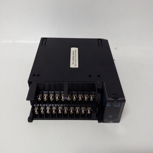
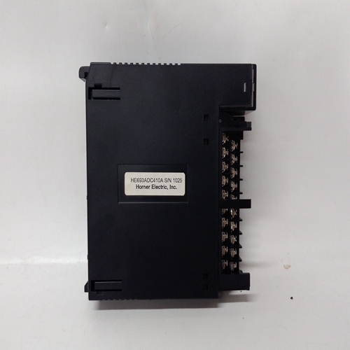
HE693ADC410A燃机电气模块
传感器连接13.1概述
警告传感器导线连接不正确可能会导致以下部件损坏:传感器和系统57两者。
注意安全传感器必须始终与系统连接57机组处于无动力状态。在其处隔离电源建立连接前的源代码。
确保所有外部直流备用电池电源也残废重要的
为了确保系统的正确运行,以及满足欧洲RFI和EMC标准,所有传感器领域电缆必须屏蔽。每个传感器的电缆屏蔽应连接至机柜保护接地。根据传感器的操作,将电缆连接到传感器并将现场电缆敷设回System 57装置。这个传感器电缆应远离干扰源如交流电力电缆、电机、机械等。
使用随装置提供的配置表上的信息以决定将哪个传感器连接到每个通道。以下章节描述了催化和4-20mA的传感器连接输入单通道控制卡。
13.2催化传感器连接
催化传感器需要三线连接和传感器文件将显示三个连接S、01和NS,它们是通常分别为棕色、白色和蓝色。此外,SensePoint可燃ppm版本还具有屏幕连接。
在现场电缆的系统57端,三根传感器导线应每个都连接到相应的匹配S、01或NS端子连接到所需单体的现场接口或中继卡
频道显示卡传感器电缆屏蔽或钢丝铠装(或编织物),
应连接到系统(保护)接地。这可能是通过使用金属电缆,在电缆进入机柜的位置实现
压盖,或通过其他合适的方式,并避免任何筛网“尾部”在机柜内。
其中电缆由单独的屏蔽、护套和电线组成铠装(或编织),铠装应在机柜处连接
应连接到保护接地和屏蔽护套的入口至现场接口/继电器卡的接地端子或至适用于仪器接地点。
可燃物传感器、接线盒和接线盒连接
注:如果传感器局部接地,则接地螺柱或通过传感器外壳接地或安装,为避免接地回路,电缆的屏蔽护套应仅为连接在一端,即在传感器处或在接口/中继卡处。
SENSOR CONNECTIONS
13.1 General
WARNING
Incorrect connection of the sensor wires may cause damage to
both the sensor and System 57.
CAUTION
The sensors connections must always be made with the System
57 unit in an unpowered state. Isolate power supplies at their
source before making connections.
Ensure that any external dc backup battery supply is also
disabled.
IMPORTANT
In order to ensure the correct operation of the system and to
meet European Standards for RFI and EMC, all sensor field
cables must be screened. The cable screen of each sensor
should be connected to the cabinet protective earth.
Connect the cabling to sensors in accordance with the Sensor Operating
Instructions and run the field cables back to the System 57 unit. The
sensor cables should be routed away from sources of interference
such as ac power cables, motors, machinery etc.
Use the information on the configuration sheet provided with the unit
to decide which sensor to connect to each channel. The following
sections describe the sensor connections for the Catalytic and 4 - 20mA
input Single Channel Control Cards.
13.2 Catalytic Sensor Connections
Catalytic sensors require a three wire connection and the sensor
documentation will indicate three connections S, 01 and NS, which are
usually brown, white and blue respectively. In addition, the SensePoint
combustible ppm version also has a screen connection.
At the System 57 end of the field cable, the three sensor wires should
each be connected to the respective matching S, 01 or NS terminal on
the Field Interface or Relay Card that is attached to the required Single
Channel Display Card
The sensor cable screen or steel wire armour (or braid), as appropriate,
should be connected to the system (protective) earth. This can be
achieved where the cable enters the cabinet by using a metal cable
gland, or by other suitable means, and avoiding any screen 'tails'
within the cabinet.
Where the cable consists of a separate screen sheath and wire
armour (or braid), the armour should be connected, at the cabinet
entry, to the protective earth and the screen sheath should be connected
to the GROUND terminal of the Field Interface/Relay Card or to a
suitable instrument earth point.
Combustible Sensor, Junction Box and Terminal Block Connections
Note: Where a sensor is earthed locally, either to the Earth Stud or through the sensor casing
or mounting, to avoid earth loops the screen sheath of the cable should only be
connected at one end, i.e., at the sensor or at the Interface/Relay Card.

