


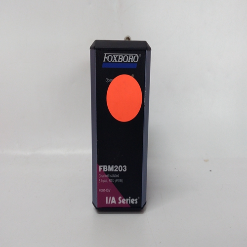
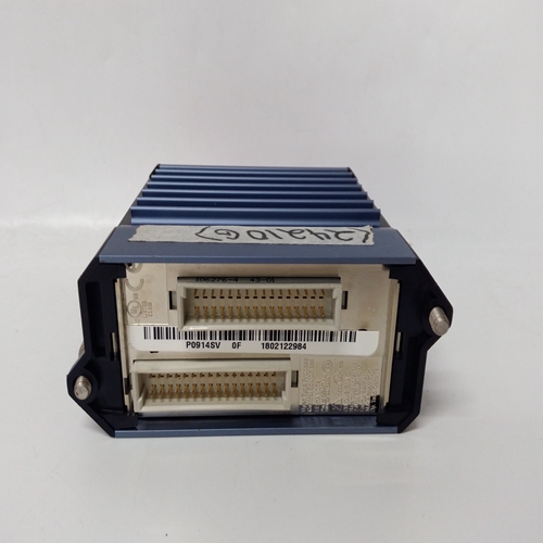
FOXBORO FBM203输入输出模块
传感器安装
11.1概述始终根据传感器的工作情况安装传感器说明书
通常,用于比空气轻的气体的传感器应位于高于空气的气体的高液位和传感器应位于:低水平。
请勿安装传感器:
a、 其中正常气流可能被阻碍。
b、 可能存在静态气穴的房间角落。
c、 靠近热源,如对流加热器。
务必安装传感器:
a、 尽可能靠近待检测的潜在气体源以便给出最大可能的警告。
b、 以便它们可用于维护工作。11.2传感器线路电阻
传感器的位置应确保电缆的线路电阻
不超过允许的最大值。该表提供了以下内容的快速指南:
特定传感器允许的最大电缆长度,当通过各种尺寸的绞合铜导线电缆连接到系统57以最小直流输入电压运行。表中的数字为最大值提供了有用的参考指南
然而,在许多情况下,电缆长度较长可能被使用。例如,其中dc输入电压高于最小值。在里面在这些情况下,需要进行更详细的分析以确定:最大线路电阻。
以下各节概述了如何计算最大线催化传感器、回路供电传感器和变送器的电阻
由系统57供电。电缆指南见第11.3节选择催化传感器催化传感器电缆的最大线路电阻不同根据安装的传感器类型的电流和电压要求。
它还受到端子S之间允许的最大10V电压的限制以及在现场接口/中继卡处的NS。
最大线路回路电阻计算如下:
10-VsRL=s
式中:RL=总线路电阻(欧姆)Vs=传感器电压(V)
s=传感器电流(A)
11.5 4-20mA回路供电传感器:
4-20mA回路供电电缆的最大线路电阻
传感器随传感器类型的电压驱动要求而变化
安装。它还受到20V最大环路驱动电压的影响。
最大线路回路电阻计算如下:
20-VsRL=0.025
式中:RL=总线路电阻(欧姆)Vs=最小传感器工作电压(V)
SENSOR INSTALLATION
11.1 General
Always install the sensors in accordance with the Sensor Operating
Instructions.
In general, sensors for lighter than air gasses should be located at a
high level and sensors for heavier than air gasses should be located at
a low level.
Do not install the sensors:
a. Where the normal air flow may be impeded.
b. In corners of rooms where static air pockets may exist.
c. Near sources of heat such as convector heaters.
Do install the sensors:
a. As close as possible to the potential source of gas to be detected in
order to give the maximum possible warning.
b. So that they are accessible for maintenance work.
11.2 Sensor Line Resistance
Sensors should be located such that the line resistance of cable does
not exceed the maximum permitted. The table gives a quick guide to
the maximum cable lengths permitted for specific sensors, when
connected by stranded copper conductor cables of various sizes to a
System 57 running at the minimum dc input voltage.
The figures in the table provide a useful reference guide to maximum
cable lengths, however, in many circumstances longer cable runs can
be used. eg. Where the dc input voltage is higher than the minimum. In
these circumstances a more detailed analysis is required to determine
maximum line resistance.
The following sections outline how to calculate the maximum line
resistance for catalytic sensors, loop powered sensors and transmitters
powered from the System 57. See Section 11.3 for a guide on cable
selection.Catalytic Sensors
The maximum line resistance of cabling for a catalytic sensor varies
with the current and voltage requirements of the type of sensor installed.
It is also subject to a maximum of 10V permitted across terminals S
and NS at the Field Interface/Relay Card.
Maximum line loop resistance is calculated as follows:
10 - Vs
RL =
I
s
Where: RL = Total Line Resistance (ohms)
Vs = Sensor Voltage (V)
I
s = Sensor Current (A)
11.5 4-20mA Loop Powered Sensors:
The maximum line resistance of cabling for a 4 - 20mA loop powered
sensor varies with the voltage drive requirements of the type of sensor
installed. It is also subject to a 20V maximum loop drive voltage.
Maximum line loop resistance is calculated as follows:
20 - Vs
RL =
0.025
Where: RL = Total Line Resistance (ohms)
Vs = Minimum Sensor Operating Voltage (V)

