


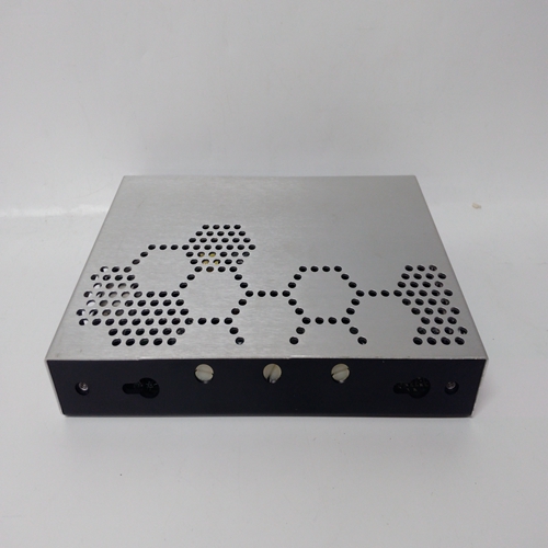
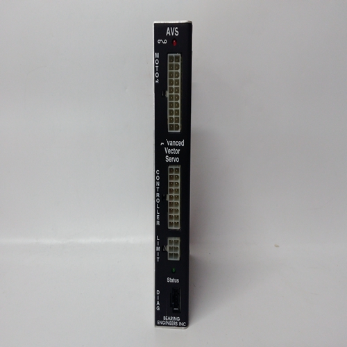
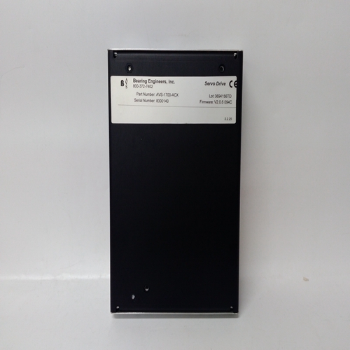
AVS 800-372-7402控制模块
要计算功率需求:
(1) 在列中输入系统中使用的每种类型的设备数量B
(2) 乘以C列所示的单位功率。
(3) 在D列中输入结果。
(4) 将D列相加,计算所需的总功率。
通风系统57控制系统为大量
通道在非常小的空间中。在人口密集的机架中,尤其是配置有许多催化输入控制卡或继电器的
正常通电运行时,散热可能:导致机架内和区域内的温度显著升高靠近机架。
因此,必须仔细考虑热规划。到实现最大程度的对流冷却,始终确保空气能够通过机架和电源自由流动。不要堵塞通风口机架顶部和底部的孔,如有可能,将控件隔开卡片均匀地放在架子上。
建议在调试期间,工作温度:检查机架的温度,以确保最高工作温度不超过55°C。在某些情况下,添加强制空气可能需要通风。
允许的最大电源配置,不提供:
8路机柜的附加通风为100w,16路机柜的额外通风为200w内阁
预备确保每个控制卡与建议的传感器兼容/与该控制卡相连的变送器。
确保在使用交流至直流电源装置的情况下,这是与本地市电交流电源电压兼容,且PSU额定功率足以满足其单独的系统负载。
注:05701-A-0405和05701-A-0406型交流至直流电源供电单元运行,无需输入电压
从85V到264V、47Hz到440Hz交流电源的调整输入。
机柜安装
可提供两个机柜,一个8向机柜可容纳8向机柜访问机架和16路,以容纳16路前访问支架
机柜必须固定在墙上或其他合适的垂直位置表面,如下所示:
(1) 根据需要敲出底部压盖板入口安装机柜前,系统布线并安装密封套。
(2) 将提供的四个安装支架连接到机柜。
(3) 使用所示尺寸标记支座的位置安装表面上的孔。
(4) 如有必要,钻孔并堵上安装孔。
To calculate the power requirement:
(1) Enter the number of devices of each type used in the system in column
B.
(2) Multiply by the unit power shown in column C.
(3) Enter the result in column D.
(4) Add up column D to calculate the total power required.
VENTILATION
The System 57 Control System provides the facility for a large number of
channels in a very small space. In heavily populated racks, especially
those with many catalytic input control cards or relays configured for
normally energised operation, it is possible for the heat dissipation to
cause a significant rise in temperature both within the rack and in an area
close to the rack.
As such, careful consideration must be given to thermal planning. To
achieve most from the convection cooling, always ensure that the air can
flow freely through the rack and power supply. Do not obstruct the air vent
holes in the top and bottom of the rack and if possible space the control
cards evenly within the rack.
It is recommended that during commissioning the operating temperature
of the rack is checked to ensure that the maximum operating temperature
of 55°C is not exceeded. In some cases the addition of forced air
ventilation may be required.
Maximum power supply configuration allowed without provision for
additional ventilation is 100w for 8 way cabinet and 200w for 16 way
cabinet.
PRELIMINARIES
Ensure that each control card is compatible with the proposed sensor/
transmitter to be connected to that control card.
Ensure that where an AC to DC Power Supply Unit is to be used, this is
compatible with the local mains ac supply voltage and that the PSU
power rating is adequate for its individual system load.
Note: The model 05701-A-0405 and 05701-A-0406 AC to DC Power
Supply Units operate, without the requirement of input voltage
adjustments, from an 85V to 264V, 47Hz to 440Hz ac supply
inputs.
CABINET INSTALLATION
Two cabinets are available, an 8-way to accommodate the 8-way front
access rack and a 16-way to accommodate the 16-way front access
rack.
The cabinet must be secured to a wall, or other suitable vertical
surface, as follows:
(1) Knock out the bottom gland-plate entries as appropriate for the
system cabling and fit the glands before mounting the cabinet.
(2) Attach the four mounting brackets provided to the cabinet.
(3) Using the dimensions shown mark the position of the mounting
holes on the mounting surface.
(4) Drill and wall plug the mounting holes as necessary.

