


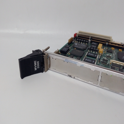
MVME5500输出卡件
检查执行器连杆与燃油控制任何空转、束缚或超载。验证燃料是否稳定适当值的压力。
按照适当的执行机构检查执行机构手册原动机不工作正确地原动机可能导致速度变化。手动控制发动机至确定原动机是否不稳定,或调速器控制。验证调整是否正确燃料控制连杆的。
输入电压低
检查电源电压,至少应为低压控制装置上的20 Vdc和90 Vdc在高压控制上为88 Vac。速度设定控制不调节速度。故障额定速度或速度微调电位计。
用跳线替换速度微调进行检查并与主速度一起设置速度电位计。原动机未接收燃料as州长要求的。
如果致动器的电压最大(最小对于反向作用),目视确定
致动器轴处于最大位置。如果是否则,指示执行器故障,或
连杆或燃油系统受限。速度设置不相等。确保所有机组的速度设置为“否”负载相同。
负载增益电压不相等。原动机在单机组配置,必须设置负荷增益在6.0VDC下。参见中的“负载增益调整”
断路器辅助触点或者下垂触点断开。
检查辅助断路器和下垂联络。检查来自的18至40 Vdc低压控制上的端子14至15。
高压控制只能测量从14号端子到18号端子,如果接近
超驰故障:速度信号触点不存在关闭
负载感应和定相不当。执行第3章中的定相程序。之间的循环电流发电机。
请参阅相应的电压调节器手册原动机维持恒速(等时)。
致动器。如果致动器有球头备份,验证
其液压调速器部分,速度
设置和速度降调整为:正确设置(参见适用的调速器手动)。
原动机。如果仅在满负荷点附近出现下降,原动机可能不是产生燃料所需的动力
控件或正在过载。要么是
如果燃油控制处于最大值,则指示位置
Check actuator linkage to fuel controlling
mechanism for any lost motion, binding, or
excessive loading. Verify a steady fuel
pressure of proper value.
Check actuator per appropriate actuator
manual.
Prime mover not operating
properly.
Prime mover may be causing speed
variations. Control engine manually to
determine if instability is in prime mover or
governor control. Verify proper adjustment
of fuel control linkage.
Input voltage low. Check supply voltage, It should be at least
20 Vdc on low voltage controls and 90 Vdc
or 88 Vac on high voltage controls.
Speed-setting
control does not
regulate speed.
Faulty RATED SPEED or Speed
Trim potentiometer.
Check by replacing Speed Trim with jumper
and setting speed with main speed
potentiometer. Prime mover not receiving fuel as
called for by the governor.
If voltage to actuator is maximum (minimum
for reverse-acting), visually determine if
actuator shaft is at maximum position. If it is
not, an actuator problem is indicated, or the
linkage or fuel system is restricted. Unequal speed settings. Be sure that speed settings of all units at no
load are identical.
Unequal load-gain voltages. With the prime mover operating in single
unit configuration, LOAD GAIN must be set
at 6.0 Vdc. See “Load Gain Adjustment” in
Chapter 3.
Circuit breaker auxiliary contact
or droop contact is open.
Check auxiliary circuit breaker and droop
contacts. Check for 18 to 40 Vdc from
terminal 14 to 15 on low voltage controls.
NOTE
High voltage controls can only be measured
from terminal 14 to 18 if the close to
override failed speed signal contact is not
closed.
Improper load-sensing phasing. Perform phasing procedure in Chapter 3.
Circulating currents between
generators.
Refer to appropriate voltage regulator
manual.
Prime mover does
not maintain
constant speed
(isochronous).
Actuator. If actuator has a ballhead backup, verify
that its hydraulic governor section, speed
setting, and speed droop adjustments are
properly set (see the applicable governor
manual).
Prime mover. If droop occurs near the full-load point only,
it is possible the prime mover is not
producing the power called for by the fuel
control, or is being overloaded. Either is
indicated if the fuel control is at maximum
position.

