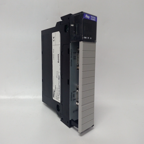
SST-PB3-CLX-RLL模块PLC卡件
如一般信息部分所述,下垂模式允许以下操作:
无限总线上或与其他发动机发电机组并联的发电机使用液压机械调速器。在降速时,速度随负载的变化而变化发电机发生变化。负载增加导致速度降低。这个速度变化或下降量以百分比表示,由下垂电位计如图4-5所示。2301A负载共享和速度控制由直流-直流隔离供电
电源,允许在宽电压范围内运行,无需产生过多的热量。这种隔离保护系统免受干扰
由接地回路引起,特别是通过负载共享线路,并允许与伍德沃德负荷分担控制的早期模型进行负荷分担。
第五章。故障排除
以下故障排除指南有助于隔离控制装置的故障
接线盒、致动器、设备接线或其他地方。超出此级别的故障排除是:
当有完整的控制测试设施可用时才推荐。错误的电压可能会损坏控制器。更换时
a控制,检查电源、电池等是否正确
电压故障排除程序
表5-1是隔离系统问题的一般指南。本指南假设:
系统接线、焊接连接、开关和继电器触点,以及输入和输出连接正确,工作状态良好。使按指定顺序检查。各种系统检查假设
检查已正确完成。准备在启动时紧急停机
发动机、涡轮机或其他类型的原动机,以防止失控或超速,可能造成人身伤害、生命损失,或财产损失。
表6-1.故障排除症状、原因和补救措施原动机不会开始致动器不移动到启动燃料位置
注意如果致动器移动到起始位置,a问题原动机燃料指示供应。
电源电压极性反转(仅直流)或无电源电压。检查端子16的电压是否正确(+)至15(–)。如果极性为不正确(仅限dc)。
执行器对输入无响应来自控制的信号。
注意液压执行器必须具有:油压和齿轮旋转至操作(响应)。
如果控制处有电压输出端子20(+)和21(-),但致动器不移动,连接至执行器的导线应检查有无开路或短路。具有EG3P执行器,记住配合插头的端子C和D应:跳起来。检查执行机构的电阻。
伍德沃德致动器上的线圈电阻为:大约35Ω. (与线索一起阅读:T20和T21断开。)
起动燃油限制设置过低。顺时针转动起动燃油限制,直到起动移动器启动。
致动器或连杆。检查执行机构和连杆是否正确安装和操作。问题可能是供油、旋转方向、不足排水连杆,磨损的执行机构或调整不当。
As mentioned in the general information section, droop mode allows operation of
a generator on an infinite bus or in parallel with other engine generator units
using hydromechanical governors. In droop, speed changes as the load on the
generator changes. An increase in load results in a decrease in speed. The
amount of speed change or droop is expressed in percent, and is set by the
DROOP potentiometer shown in Figure 4-5.
The 2301A Load Sharing and Speed Control is powered by a dc-dc isolated
power supply, which allows operation over a wide voltage range without
generating excessive heat. This isolation protects the system from interference
caused by ground loops, particularly through the load-sharing lines, and allows
load sharing with earlier models of Woodward load-sharing controls.
Chapter 5.
Troubleshooting
The following troubleshooting guide is an aid in isolating trouble to the control
box, actuator, plant wiring, or elsewhere. Troubleshooting beyond this level is
recommended ONLY when a complete facility for control testing is available.
The control can be damaged with the wrong voltage. When replacing
a control, check the power supply, battery, etc., for the correct
voltage.
Troubleshooting Procedure
Table 5-1 is a general guide for isolating system problems. This guide assumes
that the system wiring, soldering connections, switch and relay contacts, and
input and output connections are correct and in good working order. Make the
checks in the order indicated. Various system checks assume that the prior
checks have been properly done.
Be prepared to make an emergency shutdown when starting the
engine, turbine, or other type of prime mover, to protect against
runaway or overspeed with possible personal injury, loss of life, or
property damage.
Table 6-1. Troubleshooting
Symptom Cause Remedy
Prime mover will not
start. Actuator not
moving to start-fuel
position.
NOTE—If the
actuator moves to
start position, a
problem with the
prime mover fuel
supply is indicated.
Supply voltage polarity reversed
(dc only), or no supply voltage.
Check for proper voltage from terminals 16
(+) to 15 (–). Reverse leads if polarity is
incorrect (dc only).
Actuator not responding to input
signal from control.
NOTE
The hydraulic actuator must have
oil pressure and gear rotation to
operate (respond).
If there is a voltage output at control
terminals 20 (+) and 21 (–), but the actuator
does not move, the wiring to the actuator
should be checked for opens or shorts. With
the EG3P actuator, remember that
terminals C and D of the mating plug should
be jumpered.
Make resistance checks at the actuator.
Coil resistance on Woodward actuators is
approximately 35 Ω. (Read with leads at
T20 and T21 disconnected.)
Start fuel limit set too low. Turn start fuel limit clockwise until prime
mover starts.
Actuator or Linkage. Check actuator and linkage for proper
installation and operation. Problems may be
oil supply, direction of rotation, insufficient
drainage. linkage, worn actuator
components, or improper adjustment.


