


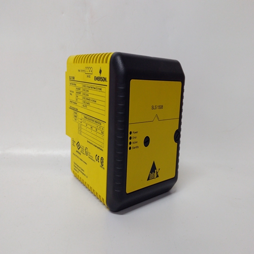
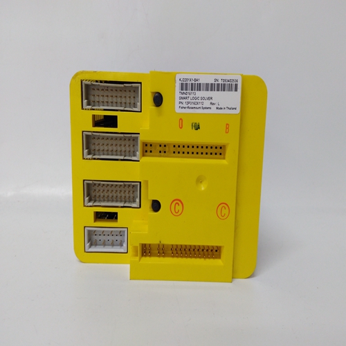
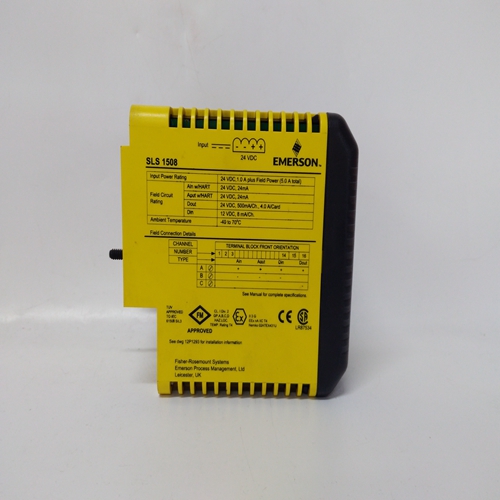

SLS1508 KJ2201X1-BA1 12P3162X112数字量卡件
外部设备的端子用于将控制装置连接到系统的接线板位于控制。包括用于连接其他外部设备的附加端子设备如图4-3所示。
平行并联有两种基本方法:降速,其中速度降低负载和等时,其中速度保持恒定。平行
图4-4所示系统包括:•负载匹配电路(1)•负载放大器电路(2)
从端子16连接的发电机联络断路器上的辅助触点(或高压控制上的端子0)到端子14用于选择同步负载共享操作。可以使用与辅助触点串联的触点选择降速或同步运行模式。
如果辅助触点或下降触点打开,则控制处于下降状态。当它们都关闭时,控制处于同步负载共享状态。
只有一台机组在线,发电机将承担可用负荷并保持以等时速度。如果其他单元在线,负载匹配电路将燃油输出校正为比例负载。
负载感应电路中的放大器计算每个相位承载的负载发电机的。每个相位上的电流负载乘以电流和电压之间的相位差,以及三相以确定总负载。
负载放大器的输出由负载增益电位计调整
如图4-5所示。通过将每个单元上的负载增益电压设置为相同
在满负荷水平,实现了比例负荷分担。不管差异在系统中的发电机组容量中,每个发电机组加载到
其容量的相同百分比。单个负载增益的最终调整电位计将补偿发电机组中的微小差异。
端子0-在高压型号上,该端子为输入端子提供+20 Vdc14、17、18、19和30。在低压型号上,不使用此端子。端子14当触点闭合时,控制处于同步状态,且负载分配线路是活动的。打开时,控制处于下降状态,负载共享线路被禁用。端子16在低压型号上,该端子提供+dc电源输入端子14、17、18、19和30,是直流电源+连接点。高压型号,该端子是交流输入端子(在交流电源上)或直流输入端子之一+连接点(直流电源上)。端子17-A触点,用于在需要停机时将输出驱动至最小燃油*跨接导线不得用于高压型号。端子18-A触点,用于超控故障转速保护电路以进行启动和起动燃油设置校准。端子19—触点闭合时从怠速加速至额定转速的触点。端子23和24是远程微调速度设置的外部装置。它也可用于手动同步或运行时加载发电机在下垂模式下。端子25和26提供了可选速度和相位匹配(SPM)的使用同步器。SPM同步器自动生成一个信号,以使离线发电机的原动机,使其频率和相位与公共汽车**
*-不要将最小燃油接触选项用作任何紧急停机序列的一部分。
**-更多信息,请参见伍德沃德手册82384,SPM-A同步器9905-002在SPM-A上。
Terminals for External Devices
Terminal blocks for wiring the control to the system are at the lower front panel of
the control. Additional terminals are included for connecting other external
devices as shown in Figure 4-3.
Paralleling
There are two basic methods used for paralleling: droop, where speed decreases
with load, and isochronous, where speed remains constant. The paralleling
system as shown in Figure 4-4 consists of:
• Load Matching circuit (1)
• a Load Amplifier circuit (2)
An auxiliary contact on the generator tie-breaker connected from terminal 16 (or
terminal 0 on high voltage controls) to terminal 14 is used to select isochronous
load-sharing operation. A contact in series with the auxiliary contact may be used
to select either the droop or isochronous mode of operation.
If either the auxiliary contact or the droop contact is open, the control is in droop.
When they are both closed, the control is in isochronous load sharing.
With only one unit on line, the generator picks up the available load and remains
at isochronous speed. If additional units are on line, the Load Matching circuit
corrects the fuel output to proportion load.
An amplifier in the load-sensing circuit computes the load carried by each phase
of the generator. The current load on each phase is multiplied by the cosine of
the phase difference between the current and the voltage, and the three phases
are added to determine the total load.
The output of the load amplifier is adjusted by the LOAD GAIN potentiometer
shown in Figure 4-5. By setting the load-gain voltage on each unit to the same
level at full load, proportional load sharing is achieved. Regardless of differences
in generator-set capacities in the system, each generator set is loaded to the
same percentage of its capacity. A final adjustment of the individual LOAD GAIN
potentiometers will compensate for minor differences in the generator sets.
Terminal 0—On high voltage models, this terminal provides +20 Vdc for input terminals
14, 17, 18, 19, and 30. On low voltage models, this terminal is not used.
Terminal 14—When contact is closed, control is in isochronous and the load sharing lines
are active. When open, control is in droop and the load sharing lines are disabled.
Terminal 16—On low voltage models, this terminal provides a +dc source for input
terminals 14, 17, 18, 19, and 30, and is the dc supply + connecting point. On high voltage
models, this terminal is either one of the ac input terminals (on ac supply) or the dc +
connecting point (on dc supply).
Terminal 17—A contact to drive the output to minimum fuel when required for shutdown.*
The jumper must not be used on high voltage models.
Terminal 18—A contact to override the failed speed protective circuit for start-up and start
fuel setup calibration.
Terminal 19—A contact to accelerate from idle to rated speed when the contact is closed.
Terminals 23 and 24—An external means of remotely fine tuning the speed setting. It
also may be used for manual synchronization or for loading the generator when operating
in droop mode.
Terminals 25 and 26—Provide for use of an optional speed and phase matching (SPM)
synchronizer. An SPM synchronizer automatically generates a signal to bias the speed of
the prime mover of an off-line generator so that its frequency and phase match those of
the bus.**
*—Do not use the minimum fuel contact option as part of any emergency stop sequence.
**—See Woodward manual 82384, SPM-A Synchronizer 9905-002, for more information
on the SPM-A.

