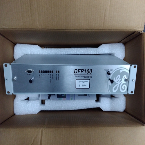
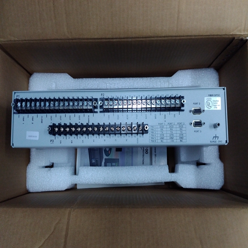
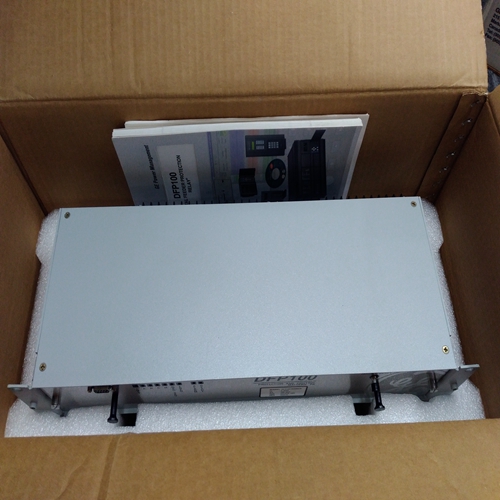
GE DFP14C1N000GB控制模块
如果满载时为6伏(或与负载成比例的较低电压小于无法获得100%),并且已检查相位,并且正确,电流互感器可能尺寸错误。满负荷时,电流互感器输出必须为3至7A(标称5A)。
可能需要降低系统中每个单元的负载信号电压在极差的系统动力学的情况下低至3V。如果您的系统
需要低至3 V的负载信号电压,请咨询伍德沃德以获取建议
寻找可能的补救办法。下垂调整当发电机组处于以下状态时,有必要调整下垂电位计:
以在下垂模式下操作。负载传感器的下降通常表示为:作为百分比,并通过以下公式计算。
%下垂=空载速度-满载速度
空载速度x100设置下垂的方法取决于发电机组的负载是否:隔离负载或无限总线。
设置隔离负载的降速
1.断开连接至端子14的下垂触点。
2.启动原动机并调整额定转速电位计空载时的额定转速。
3.施加全负荷*
4.调整下垂电位计以获得所需速度。
例如:在60 Hz下运行,在满载下57 Hz表示5%的下降。
*-如果只有50%的负载是可能的,58.5 Hz将表示5%的下降(见图3-3).
针对公用设施设置下垂使用以下步骤设置下垂和负载增益电位计:公用事业作为唯一的负载。
1.在以下情况下计算发电机的满载速度(或频率):以100%负载运行。
空载频率=额定频率x(1+下降%)
示例:额定频率=60.0 Hz
所需下垂=3%(0.03)
空载频率=60 x(1+0.03)=61.8 2。以步骤1中计算的速度空载运行发电机。记录速度设置设备的设置:
•带有铅笔标记的电位计记录设置。
•MOP或其他测量并记录速度设置值电压(控制处)。
3.将系统速度降低到额定(频率)。
4.完全顺时针预设负载增益和下降电位计(be小心不要过度扭转锅)。
如果在闭合断路器时,装置上的负载迅速增加,打开断路器并关闭机组。检查CTs和PTs。允许机组继续装载,或在不纠正此情况的情况下继续操作系统可能导致设备损坏,人员受伤或死亡。
5.同步、闭合发电机断路器,并通过将速度设置增加到步骤2中记录的设置。
步骤6和7中的调整是非线性的。更改小增量以防止过载。
6.通过转动下垂电位计增加装置上的负载逆时针旋转,直到负载增益电压读数为6.0 Vdc*。
7.通过逆时针转动负载增益电位计增加负载,直到负载处于所需的100%值。
f 6 volts at full load (or a lower voltage proportional to a load less than
100%) cannot be obtained, and the phasing has been checked and is
correct, the current transformers are probably the wrong size. The currenttransformer output must be from 3 to 7 A (5 A nominal) at full load.
It may be necessary to reduce the load-signal voltage of each unit in the system
to as low as 3 V in cases of extremely poor system dynamics. If your system
requires a load-signal voltage as low as 3 V, consult Woodward for suggestions
for possible remedies. Droop Adjustment
Adjustment of the DROOP potentiometer is necessary when the generator set is
to be operated in the droop mode. Droop in a load sensor is usually expressed
as a percentage and calculated by the following formula.
% Droop =
No Load Speed – Full Load
Speed
No Load Speed
x 100
The method of setting droop depends on whether the load of the generator set is
an isolated load or an infinite bus.
Setting Droop for an Isolated Load
1. Open the droop contact connected to terminal 14.
2. Start the prime mover and adjust the RATED SPEED potentiometer for
rated speed with no load.
3. Apply full load. *
4. Adjust the DROOP potentiometer to give the desired speed.
Example: Operating at 60 Hz, 57 Hz at full load indicates 5% droop.
*—If only 50% loading is possible, 58.5 Hz would indicate 5% droop (see Figure
3-3).
Setting Droop when Against Utility
Use the following procedure to set the Droop and Load Gain potentiometers with
the utility as the only load.
1. Calculate the fully loaded speed (or frequency) of the generator when
running at 100% load.
No Load frequency = rated frequency x (1 + droop %)
Example: Rated frequency = 60.0 Hz
Desired droop = 3% (0.03)
No Load Frequency = 60 x (1 + 0.03) = 61.8 2. Run the generator at the speed calculated in step 1, with no load. Record
the setting of your speed-setting device:
• Potentiometer—record setting with a pencil mark.
• MOP or Other—measure and record the value of the speed-setting
voltage (at the control).
3. Reduce system speed to rated (frequency).
4. Preset both the Load Gain and Droop potentiometers fully clockwise (be
careful not to overtorque the pot).
If when you close the breaker, the load on the unit increases rapidly,
open the breaker and shut the unit down. Check the phasing of the
CTs and PTs. Permitting the unit to continue to pick up load or
continuing to operate the system without correcting this condition
may cause damage to equipment, and injury or death to personnel.
5. Synchronize, close the generator breaker, and increase the load by
increasing the speed setting to the setting recorded in step 2.
The adjustments in steps 6 and 7 are non-linear. Make changes in
small increments to prevent overload.
6. Increase the load on the unit by turning the Droop potentiometer
counterclockwise until the Load Gain Voltage reads 6.0 Vdc *.
7. Increase load by turning the Load Gain potentiometer counterclockwise until
the load is at the desired 100% value.


