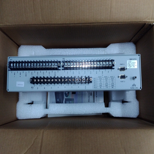
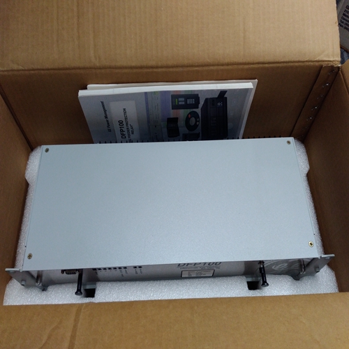
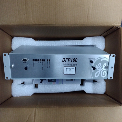
GE DFP100控制器
负载增益调整对于该程序,发电机必须同步运行,而不是平行。将直流电压表连接到端子11(–)和13(+)之间进行测量负载信号电压。
启动原动机并施加全负荷。测量负载信号电压和将负载增益电位计调整为6.0 V.*如果无法获得全负载,与负载成比例地减小负载增益。例如,在50%负载下将负载增益调整为3 V。
当在同步模式下或在隔离母线上并联时,发电机速度必须相同。如果它们不相等,则不会保持负载共享与负载变化成比例。机组之间的任何负载差异可能是:通过调整负载增益电位计进行校正。增加负载增益(顺时针转动电位计)将使发电机承载更少的负载。
如果在特定负载信号电压下并联时出现稳定性问题,通过降低负载增益来降低电压(转动电位计逆时针),并降低所有其他的负载信号电压设置系统中的发电机电压相同。当负载信号电压系统中的所有发电机减少、负载分配增益减小,并且这可能导致负载分担灵敏度的一些损失。从端子8和9上拆下A相CT导线,然后连接该相连接到产生最高正负载信号的一对端子的导线电压和产生最高正负载信号的极性电压19.解开并断开B相CT导线。连接B相CT将导线连接到负载上剩余两对CT输入端子中的一对传感器20.施加全负荷并测量负荷信号。
启动新列表并记录电压21.卸载系统,并反转系统上的B相CT导线终端*
22.施加全负载,测量负载信号,并记录该电压。
3.卸载系统,拆下B相CT导线,并将其连接到另一对端子*
24.施加全负载,测量负载信号,并记录该电压。
25.卸载系统并反转系统上的B相CT导线终端*
26.施加全负载并测量负载信号。记录该电压,以及比较列表中的四个电压。
27.卸载系统。拆下B相CT导线并将其连接到产生最高正负载信号的一对CT输入端子电压和产生最高正负载信号的极性电压解开并断开C相CT导线。将这两条导线连接到其余一对CT输入端子。
29.施加全负载,测量负载信号,并记录该电压。
30.卸载系统并反转系统上的C相CT导线终端*
31.施加全负载,测量负载信号,并记录该电压。
32.卸载并关闭系统。比较两个电压*
33.将C相CT导线连接到同一对CT输入端子,但在产生最高正负载信号电压的极性。
34.用当前端子的相位名称重新标记每条导线连接到。
35.拆下负载电阻器和接线盒。*-如果临时负载电阻不使用。
Load Gain Adjustment
For this procedure, the generator must be running isochronously and not
paralleled. Connect a dc voltmeter across terminals 11 (–) and 13 (+) to measure
the load-signal voltage.
Start the prime mover and apply full load. Measure the load signal voltage and
adjust the LOAD GAIN potentiometer for 6.0 V. * If full load is not obtainable,
decrease the LOAD GAIN proportionally to the load. For example, at 50% load
adjust the LOAD GAIN to 3 V.
When paralleled in the isochronous mode or on an isolated bus, generator
speeds must be the same. If they are not equal, load sharing will not remain
proportional as the load varies. Any difference in loads between the units can be
corrected by adjusting the Load Gain Potentiometer. Increasing the LOAD GAIN
(turning the potentiometer clockwise) will cause that generator to carry less load.
If stability problems occur when paralleled at a particular load-signal voltage,
reduce the voltage by reducing the LOAD GAIN (turn the potentiometer
counterclockwise), and reduce the load-signal voltage setting of all other
generators in the system to the same voltage. When the load-signal voltages of
all generators in a system are reduced, the load-sharing gain will be reduced,
and this may result in some loss of load-sharing sensitivity. Remove the phase A CT wires from terminal 8 and 9 and connect the phase
A wires to the pair of terminals that produced the highest positive load-signal
voltage and in the polarity that produced the highest positive load-signal
voltage.
19. Untape and disconnect the phase B CT wires. Connect the phase B CT
wires to one pair of the two remaining pair of CT input terminals on the load
sensor.
20. Apply full load and measure the load signal. Start a new list and record this
voltage.
21. Unload the system, and reverse the phase B CT wires on the same
terminals. *
22. Apply full load, measure the load signal, and record this voltage.
23. Unload the system, remove the phase B CT wires, and connect them to the
other pair of terminals. *
24. Apply full load, measure the load signal, and record this voltage.
25. Unload the system and reverse the phase B CT wires on the same
terminals. *
26. Apply full load and measure the load signal. Record this voltage, and
compare the four voltages on the list.
27. Unload the system. Remove the phase B CT wires and connect them to the
pair of CT input terminals that produced the highest positive load signal
voltage and with the polarity that produced the highest positive load signal
voltage. Untape and disconnect the phase C CT wires. Connect these two wires to
the remaining pair of CT input terminals.
29. Apply full load, measure the load signal, and record this voltage.
30. Unload the system and reverse the phase C CT wires on the same
terminals. *
31. Apply full load, measure the load signal, and record this voltage.
32. Unload and shut down the system. Compare the two voltages. *
33. Connect the phase C CT wires to the same pair of CT input terminals, but in
the polarity that produced the highest positive load-signal voltage.
34. Re-label each wire with the phase designation of the terminal that it is now
connected to.
35. Remove the burden resistors and terminal block.
*—Be sure to shut down the prime mover if the temporary burden resistors
are not used.


