


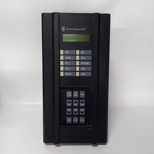
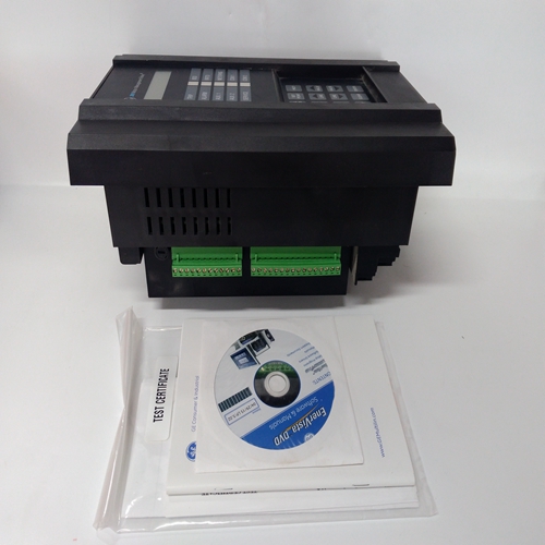
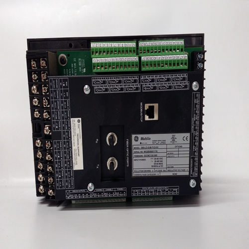
369-LO-0-M-F-E-0-0继电保护器
1:将直流电压表连接到控制端子11(-)和13(+),以测量负载信号。
2.启动原动机。发电机在等时运行模式且不并联,将发电机加载至尽可能接近满负荷可能的测量负载信号电压。
3.卸下并关闭原动机。从端子上断开导线
5,并将A相CT的两根导线连接到端子4。
4.启动原动机,施加全负荷(或步骤中获得的相同负荷2) 再次测量端子11和13处的负载信号。如果负载信号电压不低于步骤2中获得的读数的1/3,则相位不正确。卸载并关闭原动机。重新连接从端子4到端子5的A相CT导线,保持原始状态极性
如果相位不正确,则继续执行相位校正程序。如果相位显示正确,则跳过相位校正程序并继续至负载增益调整程序。
如果在完成负载增益和降速调整后控制负载对功率因数的变化极为敏感并联运行时,完成相位校正程序相位校正程序该程序要求最小功率因数为0.9。如果0.9无法获得功率因数,通过布线追踪是校正电流互感器相位的唯一方法。
当CT正确匹配时,将获得最高正电压以相位和极性连接到负载传感器端子。
以下程序:将确保电流互感器的正确连接。只有在以下情况下才需要:相位检查表明相位不正确,或负载稳定性非常差对功率因数敏感。
第一个CT与所有三个负载传感器输入端的试连接,极化通过(总共六个连接)。记录负载信号电压对于每个连接,然后将第一个CT连接到以下端子:产生最高正电压,且极性产生最高正电压。
在其余两个CT输入端子中的每个端子上尝试第二个CT极性和记录的电压。然后将第二个CT连接到产生(且极性产生)最高正极的端子电压然后在剩余的输入端子上尝试最后的CT,并记录电压。按产生的极性连接最后一个CT最高电压完成程序。
Connect a dc voltmeter to control terminals 11 (–) and 13 (+) to measure the
load signal.
2. Start the prime mover. With the generator operating in the isochronous
mode and not paralleled, load the generator to as near to full load as
possible. Measure the load-signal voltage.
3. Unload and shut down the prime mover. Disconnect the wire from terminal
5, and connect both wires from phase A CT to terminal 4.
4. Start the prime mover, apply full load (or the same load as obtained in step
2) and again measure the load signal at terminals 11 and 13. If the load
signal voltage is not 1/3 lower than the reading obtained in step 2, the
phasing is incorrect. Unload and shut down the prime mover. Reconnect
phase A CT wire from terminal 4 to terminal 5, maintaining the original
polarity.
If the phasing is incorrect, proceed to the Phase Correction Procedure.
If the phasing appears correct, skip the Phase Correction Procedure and go
to the Load Gain Adjustment procedure.
If after completing the LOAD GAIN and DROOP adjustments, the
control loading is extremely sensitive to changes in the power factor
when operating in parallel, complete the Phase Correction
Procedure.
Phase Correction Procedure
This procedure requires a minimum power factor of 0.9. If a 0.9
power factor cannot be obtained, tracing through the wiring is the
only means of correcting the current-transformer phasing.
The highest positive voltage will be obtained when the CTs are correctly matched
to the load-sensor terminals in both phase and polarity. The following procedure
will assure the correct connection of the current transformers. It is required only if
the phasing check indicates incorrect phasing, or loading stability is extremely
sensitive to the power factor.
Trial connections of the first CT to all three load-sensor inputs, polarized both
ways, are made (a total of six connections). The load-signal voltage is recorded
for each connection and the first CT is then connected to the terminals that
produce the highest positive voltage, and with the polarity that produces the
highest positive voltage.
The second CT is tried on each of the remaining two CT input terminals, in each
polarity, and the voltage recorded. The second CT is then connected to the
terminals that produce (and with the polarity that produces) the highest positive
voltage.
The last CT is then tried on the remaining input terminals, polarized both ways,
and the voltage recorded. Connecting the last CT in the polarity that produces
the highest voltage completes the procedure.

