


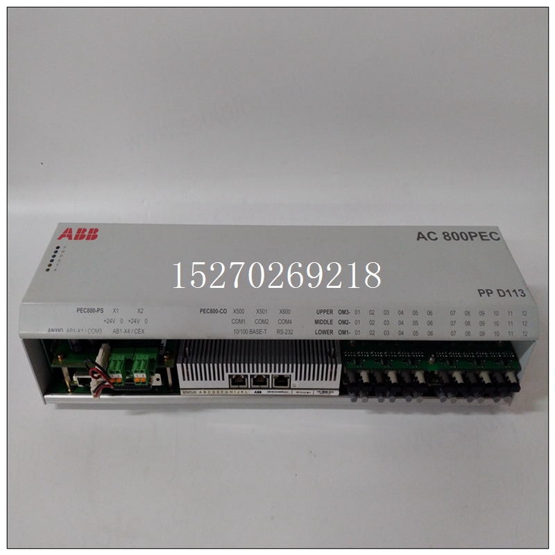


3BHE023784R1023使用产品,ABB控制模块
数据传输说明VMIVME-2511通过连接器P3和P4执行输入/输出传输,这是可从卡的正面访问。输入/输出传输通过端口实现在板上注册所需的PliT模块。使用可选缓冲器,110操作当可选输出缓冲时,VMIVME-2511是Pl/T模块的子集使用。这种情况是由于八进制收发器用于将数据缓冲到和从PIIT的每个输入/输出端口。虽然该方案将PI/T限制在110可编程性,极大地增强了PIIT操作,具有更大的驱动能力如果不使用缓冲,情况会更糟。
")
3BHE023784R1023使用产品PliT编程限制模块在编程部分进行了讨论。中断能力VMIVME-2511能够处理四个中断请求。每个PIIT模块能够发出两个请求,一个端口中断请求和一个定时器中断要求四个中断请求信号(两个来自PIiT#1,两个来自PIiT#2)为连接至68153 BIM,为两个PIiT模块提供完全中断支持。每个PI/T模块有两个可由用户编程的板载中断矢量寄存器。有关BIM和PI/T模块中断的编程见接下来的编程部分。3.5 68230并行接口定时器68230并行接口和定时器提供了多功能并行I10与各种外围设备和计算机系统的接口。每个8位端口是双缓冲,每个端口(端口A和B)有两条握手线,用于在68230之间有序地传输数据。见附录A第12、13和14页对于端口控制结构,握手定义和I/O接口时序图。每个68230的端口C可用作六条通用I10线路(C0、C1、C4-C7)C2和C3分别用作定时器时钟输入和定时器输出。或者,端口C(C4-C7)可编程为支持68230的中断结构C2和C3仍然是计时器输入引脚,C0和C1是通用引脚目的110。68230可以通过两种方式指示服务需求。处理器可以轮询端口状态寄存器,用于指示握手引脚的状态。68230可以是为中断编程。中断可能发生在两种情况中的任何一种的转换上握手引脚,HI和H2用于端口A,H3和H4用于端口B。这将进一步解释附录A第15页。CENTRONICS接口附录E中提供了质心界面的简单示例互连方案以详细的时序图显示。
110 DATA TRANSFER DESCRIPTION
The VMIVME-2511 performs I/O transfers via connectors P3 and P4 which are
accessible from the front of the card. The I/O transfers are achieved through port
registers on board the desired PliT module. With the optional buffers, the 110 operation
of the VMIVME-2511 is a subset of that of the Pl/T module when optional output buffers
are used. This is the case due to the octal transceivers used for buffering data to and
from each of the I/O ports of the PIIT. Although this scheme limits the PI/T in 110
programmability, it greatly enhances the PIIT operation with greater drive capability
than would be the case if buffering were not used. Limitations on programming the PliT
module are discussed in the programming section. INTERRUPT CAPABILITY
The VMIVME-2511 is capable of handling four interrupt requests. Each PIIT
module is capable of two requests, a port interrupt request and a timer interrupt
request. The four interrupt request signals (two from PIiT #1, and two from PIIT #2) are
connected to the 68153 BIM, giving full interrupt support for both PIiT modules. Each
PI/T module has two on-board interrupt vector registers programmable by the user.
Programming concerning interrupts for the BIM and PI/T module are found in the
programming section that follows.
3.5 THE 68230 PARALLEL INTERFACEITIMER
The 68230 Parallel Interface and Timer provides for a versatile parallel I10
interface to a wide variety of peripheral and computer systems. Each 8-bit port is
double buffered and each port (Port A and B) has two handshake lines to provide for
orderly transfer of data to and from the 68230. See Appendix A, pages 12, 13, and 14
for the port control structure, handshaking definition and I/O interface timing diagrams.
Port C of each 68230 may be used as six general purpose I10 lines (C0, C1, C4-C7)
with C2 and C3 used as the timer clock input and timer output, respectively.
Alternatively, port C (C4-C7) may be programmed to support the 68230's interrupt
structure. C2 and C3 remain the timer inputloutput pins, and C0 and C1 are general
purpose 110.
The 68230 may indicate a need for service in two ways. The processor may poll
the Port Status Register to indicate the state of the handshake pins. The 68230 may be
programmed for interrupts. The interrupts may occur on a transition of any of the two
handshake pins, HI and H2 for port A, H3 and H4 for Port B. This is further explained
on page 15 of Appendix A. CENTRONICS INTERFACE
A simple example of a centronic interface is provided in Appendix E. An
interconnection scheme is shown with a detailed timing diagram.

