


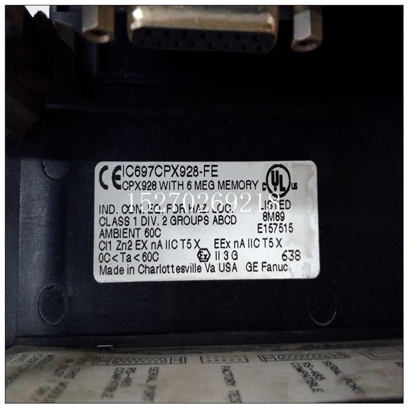

IC697CPX928-FE使用手册,GE通用电气模块
两个连接器P1和P2将VMIVME-3112板连接到VMEbus背板。连接器为96针DIN型。主连接器,P1,包含地址数据和控制线以及所有附加信号需要控制数据传输和其他总线功能。VMIVME-3112电路板使用四个用户输入/输出引脚来允许外部触发器输入和状态输出P2连接器引脚和信号分配如图5.6-1所示和表5.6-1。
")
IC697CPX928-FE使用手册P3和P4连接器是Panduit 64针阳连接器,类型120-964-033A。输入电缆的匹配Panduit连接器为内螺纹连接器,120-964-435E型。此连接器支持32单端或32差分模拟输入各有一个相关的模拟接地引脚。对于P3连接器引脚和信号分配,请参阅图5.6-2和表5.6-2。对于P4连接器引脚和信号分配,请参阅图5.6-2和表5.6-3。P3和P4接头有一个“A”行(A1到A32)和一个“C”世界其他地区(C1到C32)。所有“A”行引脚均为输入信号的高端。所有“C”行引脚是输入信号的低端。连接的首选方法模拟输入信号用于连接每个通道的高输入和低输入(差速器)。差分输入提供非常高的共模噪声通过拒绝模拟电路之间的地电位差进行拒绝发射器和VMIVME-3112板。电路板在工厂配置为接受差分输入。连接模拟输入的第二种方法称为伪差分。在这种连接方案中,只有一个接地基准被带到并在针脚C1处连接到P3连接器。这意味着所有连接来自现场的通道必须参考同一地面。此方法具有差分输入的一些优点在于它有助于抑制接地差异,但在共模噪声抑制方面不如前者。跳线J1必须安装以启用此模式。此外,输入端的SIP电阻器必须处于第5.4.3.1节所述的单端位置。连接模拟输入的第三种方法是单端输入。这该方法使用车载模拟接地作为输入信号参考。这是通常是三种方法中精度最低的。然而,在低噪音环境中当使用短布线时,这种方法会很好地工作。输入必须将sip电阻器从差速器移至单端插座(参见5.4.3.1)和跳线J2必须安装。连接器和输入/输出电缆应用指南(VMIC文件号。825-000000-006),可从提供额外信息的VMIC获得关于现场连接,圆形电缆的使用,以及兼容的连接器和布线技术。
Two connectors, P1 and P2, connect the VMIVME-3112 Board to the
VMEbus backplane. The connectors are 96-pin DIN type. The primary connector,
P1, contains the address data and control lines and all additional signals
necessary to control data transfer and other bus functions. The VMIVME-3112
Board uses four of the user I/O pins to allow an external trigger input and a status
output. The P2 connector pin and signal assignments are shown in Figure 5.6-1
and Table 5.6-1.
The P3 and P4 connectors are Panduit 64-pin male connectors, type
120-964-033A. The matching Panduit connector for the input cable is a female
connector, type 120-964-435E. This connector supports the 32 single-ended or 32
differential analog inputs each with an associated analog ground pin. For P3
connector pin and signal assignments, refer to Figure 5.6-2 and Table 5.6-2. For
P4 connector pin and signal assignments, refer to Figure 5.6-2 and Table 5.6-3.
The P3 and P4 connectors have an "A" row (A1 through A32) and a "C"
row (C1 through C32). All "A" row pins are the high side of the input signal. All "C"
row pins are the low side of the input signal. The preferred method of connecting
analog input signals is to connect both high and low inputs for each channel
(differential). Differential inputs provide for very high common mode noise
rejection by rejecting differences in ground potential between the analog
transmitter and the VMIVME-3112 Board. The board is factory configured to accept
differential inputs.
A second method of connecting analog inputs is called pseudodifferential. In this connection scheme only one ground reference is brought to the
board and connected to the P3 connector at pin C1. This implies that all connected
channels from the field must be referenced to the same ground. This method has
some of the advantages of differential inputs in that it helps reject ground
differences, but is not as good in common mode noise rejection. Jumper J1 must
be installed to enable this mode. In addition, the SIP resistors on the inputs must
be in the single-ended position as described in Section 5.4.3.1.
A third method of connecting analog inputs is single-ended inputs. This
method uses the on-board analog ground as the input signal reference. This is
generally the least accurate of the three methods. However, in a low noise
environment and when short cabling is used this method will work well. The input
sip resistors must be moved from the differential to single-ended sockets (refer to
5.4.3.1) and jumper J2 must be installed.
A Connector and I/O Cable Applications Guide (VMIC Document No.
825-000000-006) is available from VMIC that provides additional information
concerning field connections, the use of round cables, and a thorough explanation of
compatible connectors and cabling techniques.

