


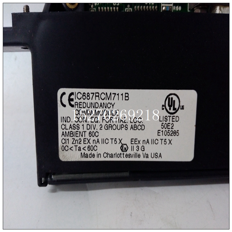
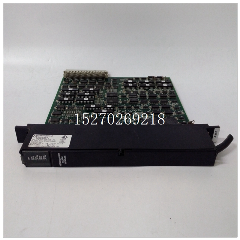
IC687RCM711B使用过程,GE燃机卡
改进的高频抑制选项,则J2为已安装,不应移除。所有RFILT输入SIP将被占用具有SIP标头。这些是0的SIP电阻器Ω. J1可能已安装,但未安装必需的这些SIP为输入源提供VME接地参考。隔离输入源(如3V/5V输入模块)需要这种配置防止高频噪声成为共模信号导致输出数据波动。
5.4.3.2输入电压范围输入电压范围由跳线J4-1、2、3控制。最大满负荷标度范围为20 V。要将满标度范围修改为10 V,请配置跳线如表5.3-1所示。所有输入电压必须在VMEbus的12 V范围内线性操作的地面。对于“一”以外的增益,所有输入电压必须为VMEbus接地10 V以内。对于单端操作,接地感应计为输入。
")
IC687RCM711B使用过程5.4.3.3双极或单极操作模拟输入的双极或单极操作通过跳线J3-1、2、3如表5.3-1所示。5.4.4外部触发跳线说明外部触发电路允许用户输入TTL电平“零”至启动A/D转换或A/D转换扫描序列。此输入必须为通过安装跳线J9和J10启用PC连接器。J9允许接地参考连接。J10启用触发信号,并标记为EXT STRT在示意图上转换L(SH6)。除了跳投,ENA EXT STRT必须在控制寄存器中设置H(D11)。该信号也被带到用户通过P2连接器。外部电路可以监测该TTL信号,当其高达逻辑“1”时,电路板已准备好进行下一个STRT转换输入以开始转换。表5.4.4-1给出了外部触发信号。内部定时器-16、32或48位定时器选择内部定时器(8254)有三个16位计数器。这三个计时器可以通过跳线生成16、32或48的最大计数长度位(请参阅第4.4.6节以确定计数器分辨率和编程)。表5.4.5-1显示了可能的跳线配置。A/D扫描序列长度跳线配置三种扫描模式(自动扫描模式、扫描轮询模式、扫描中断模式)使用J6处的跳线确定扫描多少通道。扫描始终从通道0开始,然后继续使用下一个更高的通道,直到J6与通道总数匹配已扫描。例如,出厂设置通过以下方式执行所有64个通道(0到63)在J6中编码64。J6-1是最高有效位。J6-7是最低有效位。J6-1、J6-2、J6-3、J6-4、J6-5、J6-6、J6-7的权重为64、32、16、8、4、2和1通道。安装的跳线表示“零”。表5.4.6-1给出了针对不同扫描长度安装跳线的一些示例。看见第3.6.1节了解跳线设置的限制
Frequency Rejection option is ordered, J2 is
installed and should NOT be removed. All of the RFILT input SIPs will be occupied
with SIP headers. These are SIP resistors of 0 Ω. J1 may be installed but it is not
necessary. These SIPs supply the input source with the VME ground reference.
Isolated input sources, such as the 3V/5V input modules, require this configuration
to prevent high frequency noise from becoming a common mode signal and
causing fluctuations in the output data.
5.4.3.2 Input Voltage Range
Input voltage range is controlled by jumpers J4-1, 2, 3. The maximum full
scale range is 20 V. To modify the full scale range to 10 V configure the jumpers
as indicated in Table 5.3-1. All input voltages must be within 12 V of VMEbus
ground for linear operation. For gains other than "one", all input voltages must be
within 10 V of VMEbus ground. For single-ended operation, the ground sense
counts as an input.
5.4.3.3 Bipolar or Unipolar Operation
Bipolar or unipolar operation of the analog inputs is selected with
jumpers J3-1, 2, 3 as indicated in Table 5.3-1.
5.4.4 External Trigger Jumper Description
The external trigger circuitry allows the user to input a TTL level "zero" to
start an A/D conversion or an A/D conversion scan sequence. This input must be
enabled to the PC connector by installing jumpers J9 and J10. J9 allows a ground
reference connection. J10 enables the trigger signal and is labeled EXT STRT
CONVERT L on the schematic (SH6). In addition to the jumper, the ENA EXT STRT
H (D11) must be set in the control register. This signal is also brought out to the
user via the P2 connector. External circuitry can monitor this TTL signal, and when it goes High to a logic "one" then the board is ready for the EXT STRT CONVERT L
input to begin a conversion(s). Table 5.4.4-1 gives the connector description for the
External Trigger signal.
Internal Timer - 16-, 32-, or 48-Bit Timer Selection
The internal timer (8254) has three 16-bit counters. These three timers
may be jumpered in a way to generate a maximum count length of 16, 32, or 48
bits (refer to Section 4.4.6 to determine counter resolution and programming).
Table 5.4.5-1 shows the possible jumper configurations. A/D Scan Sequence Length Jumper Configuration
The three scanning modes (AUTO SCANNING MODE, SCANNING
POLL MODE, SCANNING INTERRUPT MODE) use the jumpers at J6 to determine
how many channels to scan. Scans always begin with Channel 0 and continue
with the next higher channel until J6 matches the total number of channels
scanned. For example, the factory setting does all 64 channels (0 through 63) by
encoding 64 in J6. J6-1 is the most significant bit. J6-7 is the least significant bit.
J6-1, J6-2, J6-3, J6-4, J6-5, J6-6, J6-7 have weights of 64, 32, 16, 8, 4, 2, and 1
channels, respectively. An installed jumper signifies a "zero". Table 5.4.6-1 gives
some examples of the jumpers to be installed for different scan lengths. See
Section 3.6.1 for restrictions on jumper settings.

