


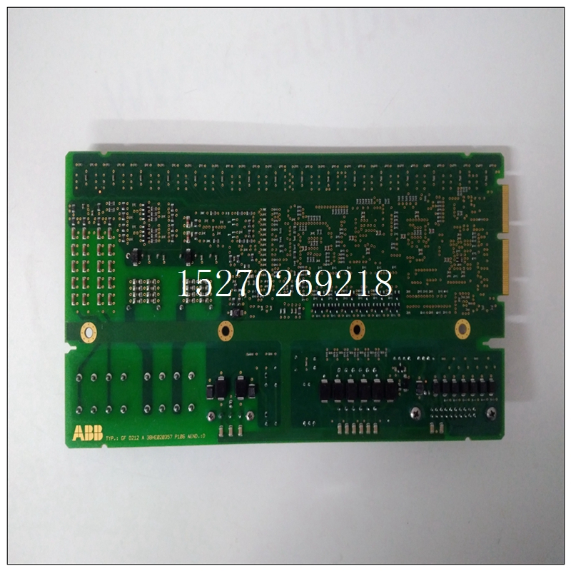
3BHE020356R0101使用书,ABB输出模块
由于8254仅存储D7至D0上显示的数据,因此两个负载需要输入完整的16位计数序列。这可以通过回顾表4.4.6-1。每个计数器寄存器必须加载两次。第一个负载设置计数的最低有效字节,第二次加载设置最高有效字节伯爵夫人。对于每个计数器,必须先写入控制字,然后写入计数已写入。4.4.7可编程间隔计时器编程顺序表4.4.7-1给出了每个计数器寄存器的地址和要加载到每个寄存器的数据的描述。
")
3BHE020356R0101使用书审查第5.4.5节关于级联计数器上的跳线安装,最大计数器长度为16、32、,或48位编程总线中断器模块(BIM)总线中断模块处理与CPU的所有中断接口板可以在任何VMEbus级别(1到7)上生成中断。当BIM编程时,以及当其中一个采用以下两种ADC操作模式:随机中断模式和扫描中断模式。
随机中断模式在完成单个a/D转换。扫描中断模式在完成2到64通道扫描时生成中断。
当上述中断条件之一发生时,BIM生成一个VMEbus 1至7级中断。必须事先启用BIM中断中断电平必须事先编程,以便BIM运行。4.4.9总线断路器模块(BIM)编程顺序BIM只使用其四个中断通道中的一个。因此,只有一个中断控制寄存器(XX10)和一个中断向量寄存器(XX18)需要进行编程。每次中断后,必须加载中断控制寄存器为下一个中断重新启用。表4.4.9-1显示了中断控制和矢量寄存器位定义。然而,对于大多数应用程序,在表4.4.9-2是正确中断操作所需的全部内容。当CPU板接受中断时,它以中断确认周期。这是一种读取循环,其中中断设备(BIM)在数据位0至7上以8位中断矢量响应。对于680X0 CPU板,该向量乘以4并添加到向量基
Since the 8254 stores only the data presented on D7 to D0, two loads
are required to enter a full 16-bit count sequence. This can be seen by reviewing
Table 4.4.6-1. Each counter register must be loaded twice. The first load sets the
least significant byte of the count and the second load sets the most significant byte
of the count. For each counter the control word must be written first, then the count
is written.
4.4.7 Programmable Interval Timer Programming Sequence
Table 4.4.7-1 gives the address of each Counter Register and a
description of the data to load into each register. Review Section 5.4.5 concerning
jumper installation on cascading counters for maximum counter lengths of 16, 32,
or 48 bitsProgramming the Bus Interrupter Module (BIM)
The Bus Interrupt Module handles all interrupt interfacing to the CPU
board. An interrupt may be generated on any VMEbus level (1 through 7).
Interrupts are generated when the BIM is programmed to do so and when one of
the following two ADC operating modes are employed: RANDOM INTERRUPT
MODE and SCANNING INTERRUPT MODE.
The RANDOM INTERRUPT MODE generates an interrupt upon the
completion of a single A/D conversion. The SCANNING INTERRUPT MODE
generates an interrupt upon the completion of a 2- through 64-channel scan.
When one of the above interrupt conditions occurs, the BIM generates a
VMEbus level 1 through 7 interrupt. The BIM interrupt must be previously enabled
and the interrupt level must be previously programmed for the BIM to operate.
4.4.9 Bus Interrupter Module (BIM) Programming Sequence
The BIM uses only one of its four interrupt channels. Therefore, only one
Interrupt Control Register (XX10) and one Interrupt Vector Register (XX18) need to
be programmed. After each interrupt the Interrupt Control Register must be loaded
to re-enable for the next interrupt. Table 4.4.9-1 shows the Interrupt Control and
Vector Registers bit definitions. However, for most applications the bits defined in
Table 4.4.9-2 are all that are necessary for proper interrupt operation.
When an interrupt is accepted by the CPU board, it responds with an
Interrupt Acknowledge cycle. This is a type of read cycle in which the interrupting
device (the BIM) responds with an 8-bit Interrupt Vector on data bits 0 to 7. For a
680X0 CPU board, this vector is multiplied by four and added to the Vector Base

