


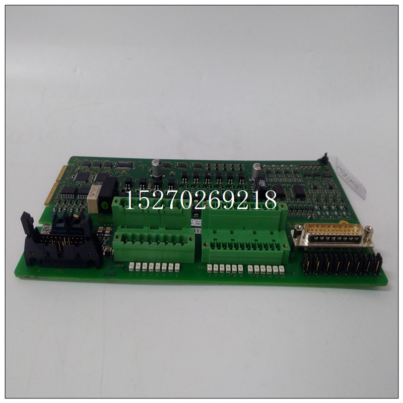
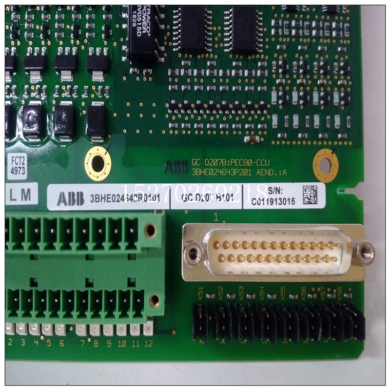
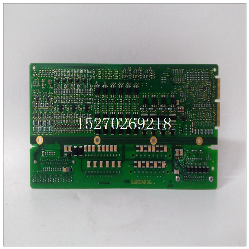
GCD207B101使用数量,ABB控制卡件
随机轮询和随机中断模式要进入随机轮询模式,三个模式控制位,模式0H到模式2H,必须在CSR中设置为“一”、“零”和“零”,分别地在此模式下,CPU板控制要转换的通道,开始转换,并轮询转换结束位以确定转换完成。由于CPU板可以选择以任意随机顺序(即CH2、CH0、CH63、,CH14。当模式控制位时,进入随机中断模式模式0H到模式2H在CSR中设置为“零”、“一”和“零”,分别地该模式基本上与随机轮询模式相同除非生成转换结束中断。
")
GCD207B101使用数量3.4.2自动扫描模式自动扫描模式在通电时自动进入板(或当模式控制位mode 0H至mode 2H设置为CSR中的“零”)。该模式对所有配置的输入进行顺序扫描(最少16个;见第5.4.6节),将输入数字化,并将结果存储在双端口寄存器。增益放大器必须在自动模式下设置为增益“1”扫描模式。一旦所有输入都数字化,该过程将在通道“零”。每当读取特定通道时,最新的数字该通道的双端口寄存器中有可用信息。此模式释放程序员从每个通道上选择并启动转换,使电路板以更快的速度数字化,并对电路板进行编程更简单。
扫描轮询和扫描中断模式扫描轮询模式类似于自动扫描模式。该模式对所有通道执行一次扫描,然后停止。扫描结束轮询状态位以确定扫描何时完成。扫描中断模式的不同之处在于,扫描结束时会对CPU板。可通过设置模式0H进入扫描轮询模式通过CSR中的模式2H分别为“一”、“一”和“零”。这个扫描中断模式可以通过设置模式0H进入CSR中的模式2H分别为“零”、“零”和“一”。总线断路器模块(BIM)处理中断功能,如第3.10段所述。3.5 ADC转换和定时无论第3.4节中描述的是哪种ADC操作模式,使用时,A/D转换顺序相同。一旦转换序列已开始(对于五种A/D操作模式中的任何一种),它包括以下内容
连续时间间隔:a、 沉降延迟b、 跟踪间隔c、 模数转换执行本节中讨论的所有ADC定时间隔由车载智能控制器自动控制。
RANDOM POLLING and RANDOM INTERRUPT MODES
To enter the RANDOM POLLING MODE, the three mode control bits,
Mode 0H through Mode 2H, must be set in the CSR to a "one", "zero" and "zero",
respectively. In this mode the CPU board controls the channel to be converted,
starts the conversion, and polls an end-of-conversion bit to determine when the
conversion is complete. This mode is entitled RANDOM because the CPU board
can select channels to be converted in any random order (i.e., CH2, CH0, CH63,
CH14…). The RANDOM INTERRUPT MODE is entered when mode control bits
Mode 0H through Mode 2H are set in the CSR to "zero", "one" and "zero",
respectively. This mode is essentially the same as the RANDOM POLLING MODE
except an end-of-conversion interrupt is generated.
3.4.2 AUTO SCANNING MODE
The AUTO SCANNING MODE is automatically entered at power-up of
the board (or when the mode control bits Mode 0H through Mode 2H are set to
"zeros" in the CSR). This mode performs a sequential scan of all configured inputs
(minimum of 16; see Section 5.4.6), digitizing the input, and storing the results in
dual port registers. The gain amplifier must be set to a gain of "one" in the AUTO
SCANNING MODE. Once all inputs are digitized, the process begins over at
channel "zero". Any time a particular channel is read, the latest digitized
information is available in that channel's dual port register. This mode frees the
programmer from selecting and starting a conversion on each channel thus,
allowing the board to digitize at a faster rate and making programming of the board
simpler.
SCANNING POLL and SCANNING INTERRUPT MODES
The SCANNING POLL MODE is similar to the AUTO SCANNING MODE.
This mode executes a single scan of all channels and then stops. An end-of-scan
status bit is polled to determine when the scan is completed. The SCANNING
INTERRUPT MODE differs in that the end-of-scan generates an interrupt to the
CPU board. The SCANNING POLL MODE may be entered by setting MODE 0H
through Mode 2H in the CSR to "one", "one" and "zero", respectively. The
SCANNING INTERRUPT MODE may be entered by setting MODE 0H through
Mode 2H in the CSR to "zero", "zero" and "one", respectively. A Bus Interrupter
Module (BIM) handles the interrupt functions and is described in paragraph 3.10. 3.5 ADC CONVERSION AND TIMING
Regardless of which ADC OPERATING MODE, described in Section 3.4,
is used, the A/D conversion sequence is the same. Once the conversion sequence
has begun (for any of the five A/D operating modes), it consists of the following
consecutive time intervals:
a. Settling Delay
b. Tracking Interval
c. Analog-to-Digital (A/D) Conversion
All ADC timing intervals discussed in this section are performed
automatically by the on-board smart controller.

