


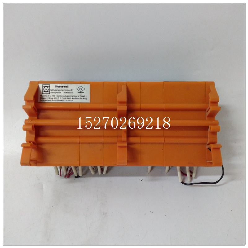
HONEYWELL FTA-T-14使用在哪里,FTA-T-14模块
功能框图VMIVME-3112板的框图如图1.2-1所示这说明了电路板的组件及其功能。未显示在方框图是提供模拟电源的直流-直流转换器(±15 V)。用户只需向电路板提供+5 V电压。引言
VMIVME-3112是一个64通道、12位模拟输入板。这个电路板具有许多内置功能,因此可以处理许多数据采集问题。例如,自动扫描模式打开通电可方便编程。在自动扫描模式下通道持续数字化并存储在双端口寄存器中。任何渠道可能随时读取以获取最新数据。VMIVME-3112是一种灵活、低成本的模拟输入板具有许多竞争产品中没有的功能。这些本节讨论了功能。
")
HONEYWELL FTA-T-14使用在哪里3.2内部职能组织VMIVME-3112分为以下功能类别,如下所示:如图3.2-1所示。详细讨论了所有VMIVME-3112函数本节。
a、 VMEbus接口b、 模数转换器(ADC)和控制逻辑
c、 模拟输入滤波器和多路复用器d、 可编程定时器
e、 总线断路器f、 板ID寄存器总线控制接口
VMIVME-3112通信寄存器的内存映射为128(十进制),16位字。寄存器是连续的,用户可以位于VMEbus的短输入/输出地址空间内的任何256字节边界。这个电路板可以由用户配置为响应短路或短路非特权总线通信或两者兼有。在每次读或写操作期间,所有VMEbus控制信号均为忽略,除非电路板选择比较器检测到车载选择跳线如图3.3-1所示,以及地址和地址背板的修改线。如果出现以下情况,则会出现适当的董事会响应:检测到有效匹配,然后打开采集器DTACK接口信号断言(驱动低)。随后删除总线主机的读写操作命令使板生成的DTACK信号返回到关闭状态。
FUNCTIONAL BLOCK DIAGRAM
A block diagram of the VMIVME-3112 Board is shown in Figure 1.2-1
which illustrates the board's components and their functions. Not shown on the
block diagram is a DC-to-DC converter which provides the analog power supplies
(±15 V). The user has only to supply +5 V to the board. INTRODUCTION
The VMIVME-3112 is a 64-Channel, 12-Bit Analog Input Board. The
board has many built-in features, resulting in a board that is capable of handling
many data acquisition problems. For example, the AUTO SCANNING MODE on
power-up allows for ease of programming. In AUTO SCANNING MODE each
channel is continually digitized and stored in a dual port register. Any channel may
be read at any time to get the latest data. The VMIVME-3112 is a flexible, low-cost
analog input board with features not found in many competing products. These
features are discussed in this section.
3.2 INTERNAL FUNCTIONAL ORGANIZATION
The VMIVME-3112 is divided into the following functional categories, as
illustrated in Figure 3.2-1. All VMIVME-3112 functions are discussed in detail in
this section.
a. VMEbus Interface
b. Analog-to-Digital Converter (ADC) and Control Logic
c. Analog Input Filters and Multiplexer
d. Programmable Timer
e. Bus Interrupter
f. Board ID RegisterVMEbus CONTROL INTERFACE
The VMIVME-3112 communication registers are memory-mapped as 128
(decimal), 16-bit words. The registers are contiguous and may be user-located on
any 256-byte boundary within the short I/O address space of the VMEbus. The
board can be user-configured to respond to either short supervisory or
nonprivileged bus communications or both.
During each read or write operation, all VMEbus control signals are
ignored unless the board-selection comparator detects a match between the
on-board selection jumpers shown in Figure 3.3-1, and the address and address
modifier lines from the backplane. The appropriate board response occurs if a
valid match is detected, after which the open collector DTACK interface signal is
asserted (driven LOW). Subsequent removal of the bus master's read or write
command causes the board-generated DTACK signal to return to the
OFF state.

