


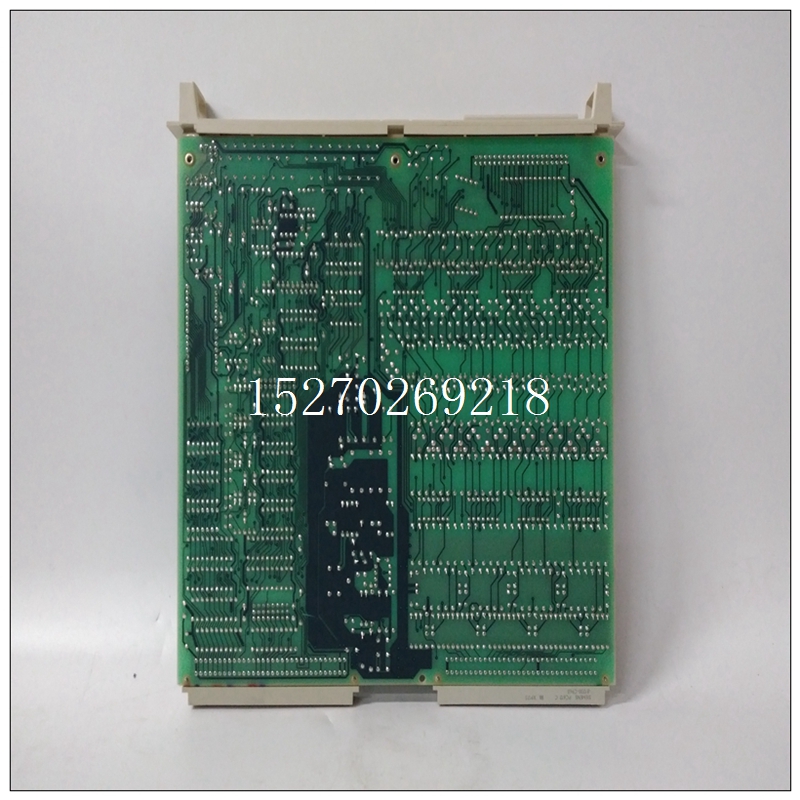

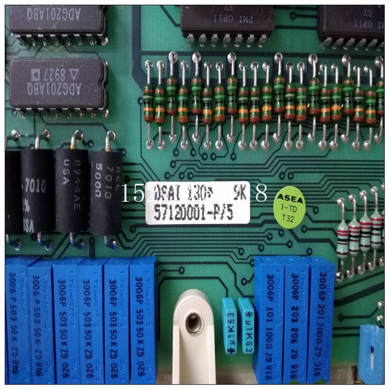
DSAI130中文PDF使用手册,ABB卡件
EIA-530连接EIA-530接口在功能上补充了EIA-232-D接口。EIA-530标准定义了该接口的机械方面,用于传输串行二进制数据,包括同步和异步。它适用于平衡(双端)和不平衡(单端)信号,并提供更高的使用相同的DB-25连接器时,数据速率高于EIA-232-D。MVME2700符合EIA-232-D规范。请注意尽管EIA-232-D标准建议使用短互连电缆长度不超过50英尺(15m),较长电缆如果在接口点(包括信号终端)不超过2500pF。接口特性在指定DTE之间串行二进制数据交换的参数时和DCE设备,EIA-530标准假设使用平衡线路,除远程环回、本地环回和测试模式线路外,它们是单端的。
")
DSAI130中文PDF使用手册平衡线路数据交换通常是优先用于不平衡线路数据交换,其中任何以下条件为准:❏ 互连电缆太长,无法有效平衡活动
❏ 互连电缆暴露于外部噪声源这可能会导致多余电压超过测量的±1V在电缆负载端,50Ω 电阻器代替发射器。
❏ 有必要尽量减少对其他信号的干扰。
❏ 可能需要反转信号(例如,加极性正负极性标记可以通过反转电缆对)。
EIA-530接口发射器和接收器参数适用于MVME2700列在下表中。正确接地需要考虑的一个重要问题是接地引脚的使用。有两个标有GND的引脚。针脚7是信号接地,必须连接到完成电路的远程设备。针脚1是机箱接地,但它必须小心使用。机箱连接至电源接地通过电源线中的绿色导线,并且必须连接到符合电气规范。
问题是,当装置连接到不同的电源插座时,地电位可能有几伏的差异。每个的If引脚1该设备通过电缆和其他设备互连,可能会产生几安培的电流。这种情况不仅对典型电缆中的小导线,但也可能产生电噪声导致数据传输错误。
EIA-530 Connections
The EIA-530 interface complements the EIA-232-D interface in function.
The EIA-530 standard defines the mechanical aspects of this interface,
which is used for transmission of serial binary data, both synchronous and
asynchronous. It is adaptable to balanced (double-ended) as well as
unbalanced (single-ended) signaling and offers the possibility of higher
data rates than EIA-232-D with the same DB-25 connector.The MVME2700 conforms to EIA-232-D specifications. Note that
although the EIA-232-D standard recommends the use of short
interconnection cables not more than 50 feet (15m) in length, longer cables
are permissible provided the total load capacitance measured at the
interface point and including signal terminator does not exceed 2500pF.Interface Characteristics
In specifying parameters for serial binary data interchange between DTE
and DCE devices, the EIA-530 standard assumes the use of balanced lines,
except for the Remote Loopback, Local Loopback, and Test Mode lines,
which are single-ended. Balanced-line data interchange is generally
employed in preference to unbalanced-line data interchange where any of
the following conditions prevail:
❏ The interconnection cable is too long for effective unbalanced
operation.
❏ The interconnection cable is exposed to extraneous noise sources
that may cause an unwanted voltage in excess of ±1V measured
differentially between the signal conductor and circuit ground at the
load end of the cable, with a 50Ω resistor substituted for the
transmitter.
❏ It is necessary to minimize interference with other signals.
❏ Inversion of signals may be required (for example, plus polarity
MARK to minus polarity MARK may be achieved by inverting the
cable pair).
EIA-530 interface transmitter and receiver parameters applicable to the
MVME2700 are listed in the following tables.Proper Grounding
An important subject to consider is the use of ground pins. There are two
pins labeled GND. Pin 7 is the signal ground and must be connected to the
distant device to complete the circuit. Pin 1 is the chassis ground, but it
must be used with care. The chassis is connected to the power ground
through the green wire in the power cord and must be connected to be in
compliance with the electrical code.
The problem is that when units are connected to different electrical outlets,
there may be several volts of difference in ground potential. If pin 1 of each
device is interconnected with the others via cable, several amperes of current could result. This condition may not only be dangerous for the
small wires in a typical cable, but may also produce electrical noise that
causes errors in data transmission.

