


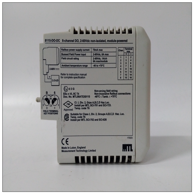
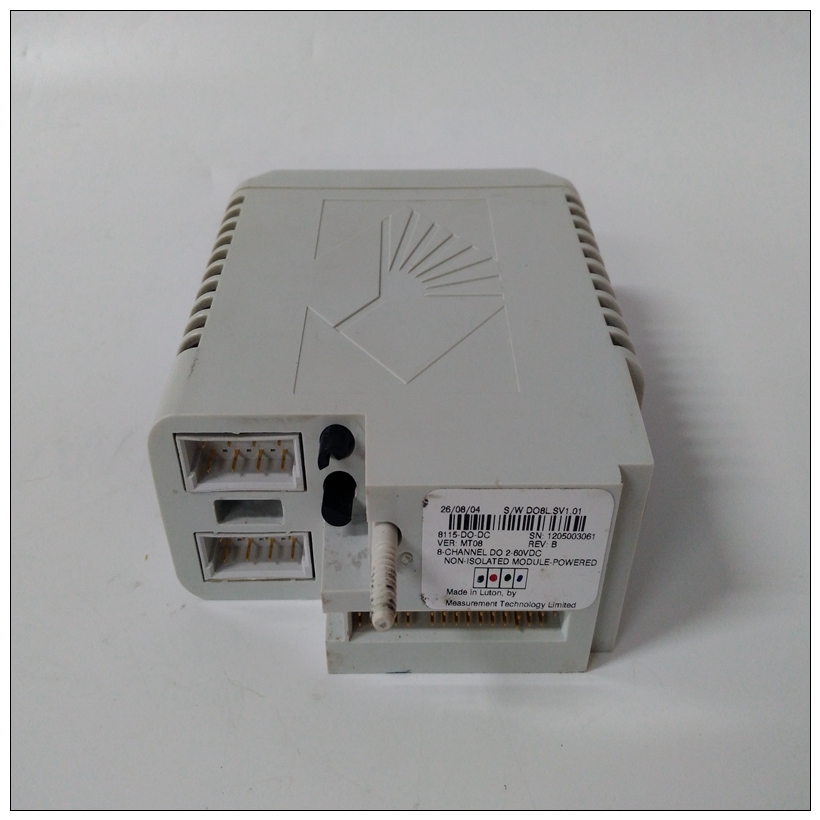
8115-DO-DC燃机模块,GE数据库
中止开关向处理器发送中断信号。中断通常用于中止程序执行并将控制返回给位于MVME2700 EPROM和闪存中的调试器固件记忆力连接到中止开关的断路器是一个边缘敏感电路,过滤以消除开关反弹。复位开关(S2)重置开关重置所有车载设备;它还驱动系统重置∗如果MVME2700是系统控制器,则发出信号。
")
8115-DO-DC燃机模块系统重置∗ 信号可能由复位开关、通电复位、看门狗超时、,或通过中其他控制寄存器(MISC\U CTL)中的控制位宇宙II ASIC。有关更多详细信息,请参阅nel指示器(DS1–DS6)MVME2700前面板上有六个LED。LED执行以下列出的功能。笔记1、复位时,灯测试功能点亮所有LED。2.因为FUS LED监控MVME2700,它不直接指示任何单个保险丝如果LED闪烁或熄灭,请检查所有保险丝(多功能开关)如第3章功能描述所述。内存映射
内存映射有三种观点:❏ 处理器(MPU总线)查看的所有资源的映射内存映射)
❏ 从PCI本地总线看板载资源的映射主机(PCI总线内存映射)
❏ VMEbus masters查看的车载资源映射(VMEbus内存映射)以下各节对MVME2700进行了概述从以上三个角度来看记忆组织。详细的内存映射可以在MVME2600/2700系列单板中找到计算机程序员参考指南,也适用于MVME2700。处理器内存映射处理器内存映射配置由
Raven bridge控制器ASIC和Falcon内存控制器芯片组。Raven和Falcon设备调整系统映射以适应给定的通过可编程地图解码器寄存器应用。系统通电时或者重置,默认处理器内存映射将接管。
ABORT Switch (S1)
The ABORT switch sends an interrupt signal to the processor. The interrupt
is normally used to abort program execution and return control to the
debugger firmware located in the MVME2700 EPROM and Flash
memory.
The interrupter connected to the ABORT switch is an edge-sensitive circuit,
filtered to remove switch bounce.
RESET Switch (S2)
The RESET switch resets all onboard devices; it also drives a SYSRESET∗
signal if the MVME2700 is the system controller. SYSRESET∗ signals may
be generated by the RESET switch, a power-up reset, a watchdog timeout,
or by a control bit in the Miscellaneous Control Register (MISC_CTL) in
the Universe II ASIC. For further details,nel Indicators (DS1 – DS6)
There are six LEDs on the MVME2700 front panel. The LEDs perform the
functions listed below.Notes
1. At reset, a lamp test function illuminates all the LEDs.
2. Because the FUS LED monitors the status of several voltages on the
MVME2700, it does not directly indicate the condition of any single
fuse. If the LED flickers or goes out, check all the fuses
(polyswitches) described in Chapter 3, Functional Description.Memory Maps
There are three points of view for memory maps:
❏ The mapping of all resources as viewed by the processor (MPU bus
memory map)
❏ The mapping of onboard resources as viewed by PCI local bus
masters (PCI bus memory map)
❏ The mapping of onboard resources as viewed by VMEbus masters
(VMEbus memory map)
The following sections give a general description of the MVME2700
memory organization from the above three points of view. Detailed
memory maps can be found in the MVME2600/2700 Series Single Board
Computer Programmer’s Reference Guide, which is also applicable to the
MVME2700.
Processor Memory Map
The processor memory map configuration is under the control of the
Raven bridge controller ASIC and the Falcon memory controller chip set.
The Raven and Falcon devices adjust system mapping to suit a given
application via programmable map decoder registers. At system power-up
or reset, a default processor memory map takes over.

