


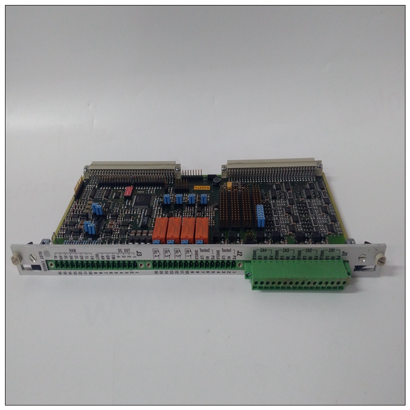
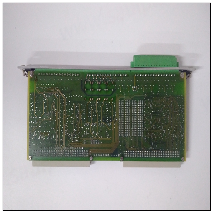
VIBRO 200-560-101-015卡件实验数据
如果出现以下情况,MVME2600和MVME712兼容型号将受损:错误地连接到MVME761转换模块,而不是更正MVME712系列电路板。MVME2603/2604型号中的注释MVME712M输入/输出模式,VMEbus的引脚分配连接器P2与其他过渡模块完全兼容MVME712系列。在这种情况下,存在可能导致死亡的危险电压设备搬运、测试和调整时要格外小心。
")
VIBRO 200-560-101-015卡件实验数据3机箱的前部或后部。(您可能需要将其他模块移入机箱为MVME712M留出空间,MVME712M具有双宽前面板。)4.将P2适配器板连接到插槽处的P2背板连接器被MVME2603/2604 VME模块占用。5、将配备MVME712M的64芯电缆从P2适配器板上的J2连接到过渡模块上的J2。一定要用接头针脚1定位电缆针脚1。避免接触集成电路的区域;静电放电会损坏这些电路
6、使用提供的螺钉将MVME712M固定在机箱中,与横向安装轨道接触良好,以将射频发射。
7、参考MVME712M的用户手册(见附录D,相关文件),50芯电缆的布线适用于您的系统配置。确保用连接器定位电缆针脚1针脚1。注意:SCSI布线可以通过多种方式进行配置,以适应各种设备和系统配置。图形1-21显示了与内部SCSI一起使用的可能配置设备。有关安装P2的更多详细信息适配器板和MVME712M转换模块,请参阅用户手册(在附录D中列出,相关文件)。8.更换机箱或系统盖,确保没有电缆挤压。用电缆将外围设备连接到面板连接器,然后重新连接将系统接至交流或直流电源,并转动设备打开电源。注:并非所有外围电缆均配备MVME712M;你可能需要制造或购买某些电缆。(最小化辐射,摩托罗拉建议外围设备使用屏蔽电缆尽可能连接。)
The MVME2600, MVME712-compatible models will be damaged if
mistakenly connected to the MVME761 transition modules instead of the
correct MVME712 family of boards.
Note In models of the MVME2603/2604 that are configured for
MVME712M I/O mode, the pin assignments of VMEbus
connector P2 are fully compatible with other transition modules
of the MVME712 series. Dangerous voltages, capable of causing death, are present in this
equipment. Use extreme caution when handling, testing, and adjusting.
3. Remove the filler panel(s) from the appropriate card slot(s) at the
front or rear of the chassis. (You may need to shift other modules in
the chassis to allow space for the MVME712M, which has a doublewide front panel.)
4. Attach the P2 adapter board to the P2 backplane connector at the slot
occupied by the MVME2603/2604 VME module.
5. Route the 64-conductor cable furnished with the MVME712M from
J2 on the P2 adapter board to J2 on the transition module. Be sure to
orient cable pin 1 with connector pin 1.
Avoid touching areas of integrated circuitry; static discharge can damage
these circuits
6. Secure the MVME712M in the chassis with the screws provided,
making good contact with the transverse mounting rails to minimize
RF emissions.
7. Referring to the user’s manual for the MVME712M (listed in
Appendix D, Related Documentation), route the 50-conductor cable
to the internal or external SCSI devices as appropriate to your
system configuration. Be sure to orient cable pin 1 with connector
pin 1.
Note The SCSI cabling can be configured in a number of ways to
accommodate various device and system configurations. Figure
1-21 shows a possible configuration for use with internal SCSI
devices. For more detailed information on installing the P2
adapter board and the MVME712M transition module, refer to
the user’s manual (listed in Appendix D, Related
Documentation).8. Replace the chassis or system cover(s), making sure no cables are
pinched. Cable the peripherals to the panel connectors, reconnect
the system to the AC or DC power source, and turn the equipment
power on.
Note Not all peripheral cables are provided with the MVME712M; you
may need to fabricate or purchase certain cables. (To minimize
radiation, Motorola recommends shielded cable for peripheral
connections where possible.)

