


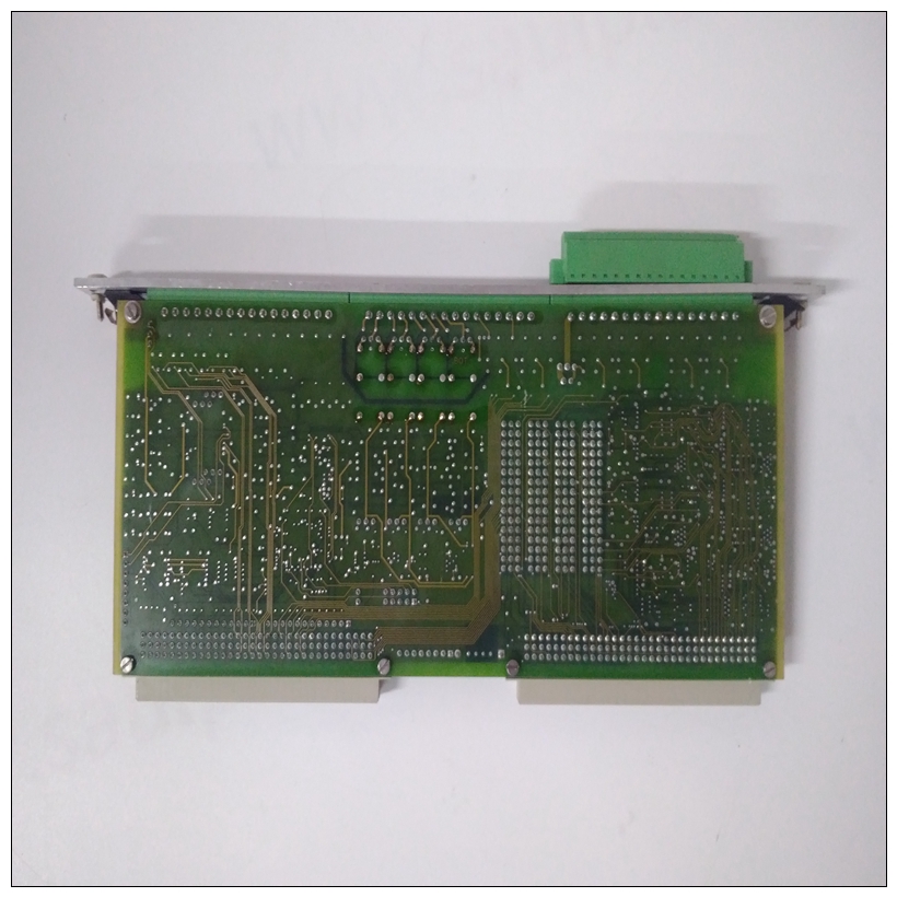
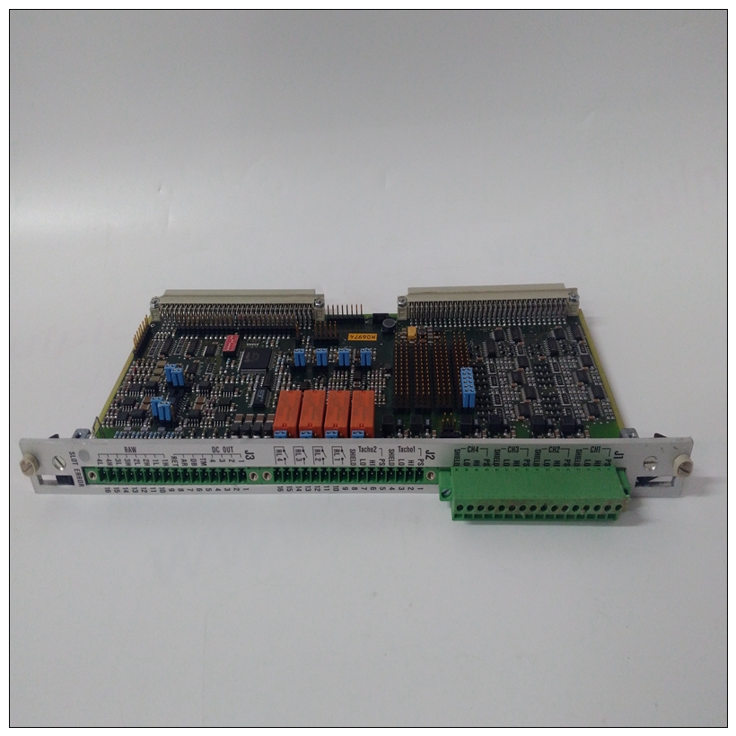
VIBRO 200-560-000-016模块,数据库
将填充板从要插入的卡槽中卸下安装MVME2603/2604。–如果您打算使用MVME2603/2604作为系统控制器,它必须占用最左边的卡槽(槽1)。系统控制器必须在插槽1中才能正确启动总线授权并确保IACK daisychain驱动器的正确操作。如果您不打算使用MVME2603/2604 as系统控制器,它可以占用任何未使用的双高卡插槽。
")
VIBRO 200-560-000-016模块4、将MVME2603/2604滑入所选卡槽。确保模块位于背板上的P1和P2连接器中。不要损坏或弯曲连接器针脚。5.用螺钉将MVME2603/2604固定在机箱中与横向安装轨道良好接触,以尽量减少射频发射。
6.在机箱背板上,删除中断确认卡头的(IACK)和总线授权(BG)跳线MVME2603/2604占用的插槽。注意一些VME背板(例如,摩托罗拉使用的那些“模块化底盘”系统)具有自动跳线功能IACK和BG信号的自动传播。第6步不适用于此类背板设计。如有必要,安装MVME712M或MVME761过渡段模块并将其连接至MVME2603/2604,如本文件的以下章节。8.将机箱或系统盖、电缆外围设备更换到根据需要,将系统重新连接到交流或直流电源,并打开设备电源。MVME712M过渡模块安装本节适用于MVME712M兼容型号的MVME2603/2604 VME模块。安装MVME2603/2604后,参考图1-21,按照以下步骤安装MVME712M过渡模块:
1、将静电带系在手腕上。连接ESD的另一端将皮带系在底盘上作为接地。静电放电带必须固定在在整个过程中,您的手腕和地面。2、执行操作系统关机。接通交流或直流电源断开并从系统中卸下交流电源线或直流电源线。拆下机箱或sy
3. Remove the filler panel from the card slot where you are going to
install the MVME2603/2604.
– If you intend to use the MVME2603/2604 as system controller,
it must occupy the left-most card slot (Slot 1). The system
controller must be in Slot 1 to correctly initiate the bus-grant
daisy-chain and to ensure proper operation of the IACK daisychain driver.
– If you do not intend to use the MVME2603/2604 as system
controller, it can occupy any unused double-height card slot.
4. Slide the MVME2603/2604 into the selected card slot. Be sure the
module is well seated in the P1 and P2 connectors on the backplane.
Do not damage or bend connector pins.5. Secure the MVME2603/2604 in the chassis with the screws
provided, making good contact with the transverse mounting rails to
minimize RF emissions.
6. On the chassis backplane, remove the INTERRUPT ACKNOWLEDGE
(IACK) and BUS GRANT (BG) jumpers from the header for the card
slot occupied by the MVME2603/2604.
Note Some VME backplanes (for example, those used in Motorola
"Modular Chassis" systems) have an auto-jumpering feature for
automatic propagation of the IACK and BG signals. Step 6 does
not apply to such backplane designs.7. If necessary, install an MVME712M or MVME761 transition
module and cable it to the MVME2603/2604 as described in the
following sections of this document.
8. Replace the chassis or system cover(s), cable peripherals to the
panel connectors as appropriate, reconnect the system to the AC or
DC power source, and turn the equipment power on.
MVME712M Transition Module Installation
This section applies to MVME712M-compatible models of the
MVME2603/2604 VME module. With the MVME2603/2604 installed,
refer to Figure 1-21 and proceed as follows to install an MVME712M
transition module:
1. Attach an ESD strap to your wrist. Attach the other end of the ESD
strap to the chassis as a ground. The ESD strap must be secured to
your wrist and to ground throughout the procedure.
2. Perform an operating system shutdown. Turn the AC or DC power
off and remove the AC cord or DC power lines from the system.
Remove chassis or sy

