


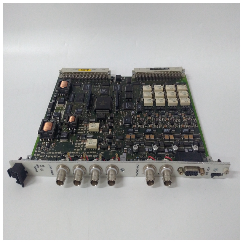
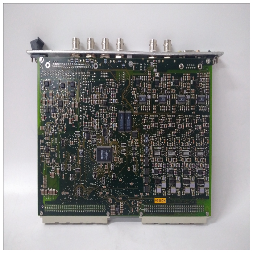
VIBRO 200-510-111-013工控卡件,参数说明
PMC承载板安装PCI夹层卡(PMC)承载板安装在RAM200上方MVME2603/2604基座上的夹层和(如果安装)PMC模块板要安装用于额外PCI扩展的PMC载体板,请参阅按照图1-20进行操作:1、将静电带系在手腕上。连接ESD的另一端将皮带系在底盘上作为接地。静电放电带必须固定在在整个过程中,您的手腕和地面。
")
VIBRO 200-510-111-013工控卡件2、执行操作系统关机。接通交流或直流电源断开并从系统中卸下交流电源线或直流电源线。根据需要卸下机箱或系统盖,以便访问VME模块。图1-20。PMC载体板在MVME2603/2604上的放置5.卸下位于上前角的LED模块螺钉基板。在其位置6安装一个短(0.394英寸)支架。在基板的其他三个角落,安装长(0.737英寸)对峙。
7、将PMC承载板放置在基板顶部。连接器在承载板的底面上,应与上相应的接头J5(位于P1和P2之间)MVME2603/2604。
8.将四个短十字螺钉穿过拐角处的孔在MVME2603/2604上的支架上。拧紧螺钉。
9.将MVME2603/2604组件重新安装到其正确的卡槽中。是确保模块正确安装在背板连接器中。不要损坏或弯曲接头针脚。10.更换机箱或系统护盖,将系统重新连接到交流或直流电源,并打开设备电源。MVME2603/2604 VME模块安装安装夹层板并正确配置标头后,按照以下步骤在VME机箱中安装MVME2603/2604:1、将静电带系在手腕上。连接ESD的另一端将皮带系在底盘上作为接地。静电放电带必须固定在在整个过程中,您的手腕和地面。
2、执行操作系统关机。接通交流或直流电源断开并从系统中卸下交流电源线或直流电源线。根据需要卸下机箱或系统盖,以便访问VME模块。
PMC Carrier Board Installation
PCI mezzanine card (PMC) carrier boards mount above the RAM200
mezzanine and (if installed) PMC module on the MVME2603/2604 base
board. To install a PMC carrier board for additional PCI expansion, refer
to Figure 1-20 and proceed as follows:
1. Attach an ESD strap to your wrist. Attach the other end of the ESD
strap to the chassis as a ground. The ESD strap must be secured to
your wrist and to ground throughout the procedure.
2. Perform an operating system shutdown. Turn the AC or DC power
off and remove the AC cord or DC power lines from the system.
Remove chassis or system cover(s) as necessary for access to the
VME modules.Figure 1-20. PMC Carrier Board Placement on MVME2603/2604
5. Remove the LED module screw located at the upper front corner of
the base board. Install a short (0.394 inch) standoff in its place6. At the other three corners of the base board, install long (0.737 inch)
standoffs.
7. Place the PMC carrier board on top of the base board. The connector
on the underside of the carrier board should connect smoothly with
the corresponding connector J5 (located between P1 and P2) on the
MVME2603/2604.
8. Insert the four short Phillips screws through the holes at the corners
of the carrier board, into the standoffs on the MVME2603/2604.
Tighten the screws.
9. Reinstall the MVME2603/2604 assembly in its proper card slot. Be
sure the module is well seated in the backplane connectors. Do not
damage or bend connector pins.
10. Replace the chassis or system cover(s), reconnect the system to the
AC or DC power source, and turn the equipment power on.
MVME2603/2604 VME Module Installation
With mezzanine board(s) installed and headers properly configured,
proceed as follows to install the MVME2603/2604 in the VME chassis:
1. Attach an ESD strap to your wrist. Attach the other end of the ESD
strap to the chassis as a ground. The ESD strap must be secured to
your wrist and to ground throughout the procedure.
2. Perform an operating system shutdown. Turn the AC or DC power
off and remove the AC cord or DC power lines from the system.
Remove chassis or system cover(s) as necessary for access to the
VME modules.

