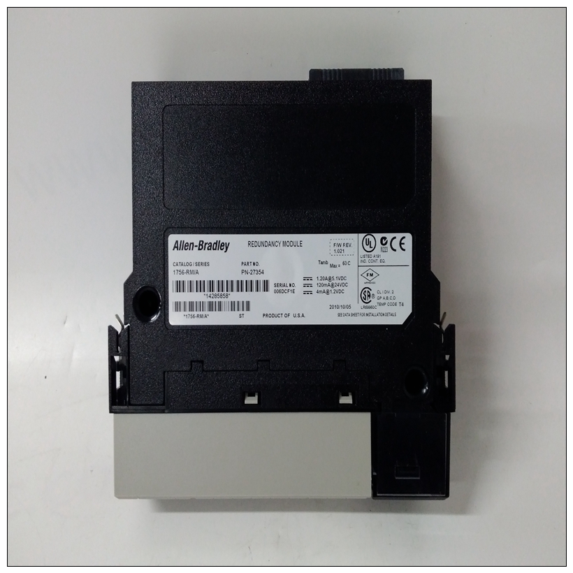
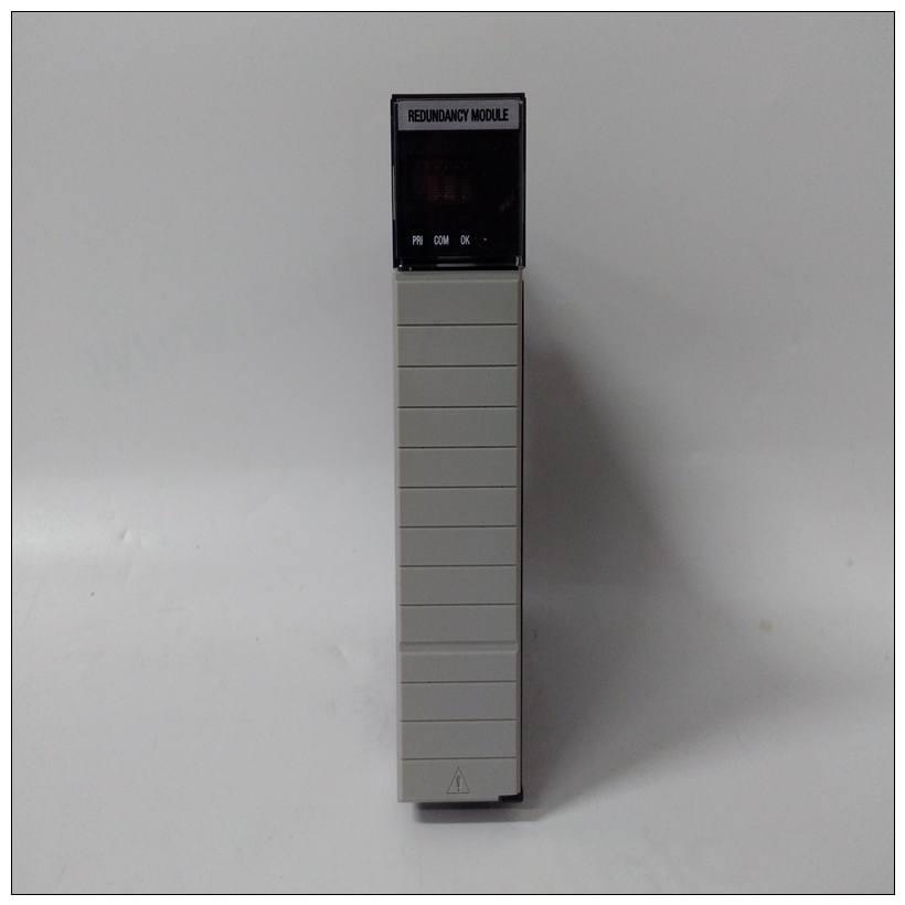
1756-RM模块,A-B使用书
MVME761过渡模块准备MVME761转换模块(图1-12)和P2适配器板是与MVME2603/2604基板一起使用。MVME761的功能包括:❏ 并行打印机端口(符合IEEE 1284-I)
❏ 支持10BaseT/100BaseTX连接的以太网接口
❏ 两个EIA-232-D异步串行端口(标识为COM1和前面板上的COM2)
❏ 两个同步串行端口(前端的串行3和串行4面板),可配置EIA-232-D、EIA-530、V.35或X.21协议❏ 两个60针串行接口模块(SIM)连接器,用于配置串行端口3和4MVME761的P2

1756-RM模块适配器板的功能包括:
❏ 一个50针连接器,用于连接SCSI设备的SCSI电缆
❏ 跳线可选SCSI端接电阻器
❏ 由+5V直流电源开发的熔断SCSI终端电源接头P2处
❏ 连接MVME761串行端口1和2的64针3M连接器在MVME2603/2604基板的MVME761兼容型号上,配置异步串行端口(串行端口1和2)永久作为数据电路终端设备(DCE)。港口配置如第1-29页图1-13所示。串行端口3和4的配置同步串行端口、串行端口3和串行端口4是可通过串行接口模块(SIM)组合进行配置选择和跳线设置。下表列出了SIM卡连接器和对应于每个同步串行端口的跳线头。端口3路由至板连接器J7。端口4在板上可用接头J8。有八个串行接口模块可用:❏ EIA-232-D(DCE和DTE)❏ EIA-530(DCE和DTE)❏ 五、 35(DCE和DTE)❏ 十、 21(DCE和DTE)您可以为上述任何串行协议配置串行端口3和4通过安装适当的串行接口模块并设置相应的跳线。SIM卡可以根据需要单独订购。
MVME761 Transition Module Preparation
The MVME761 transition module (Figure 1-12) and P2 adapter board are
used in conjunction with the MVME2603/2604 base board.
The features of the MVME761 include:
❏ A parallel printer port (IEEE 1284-I compliant)
❏ An Ethernet interface supporting 10BaseT/100BaseTX connections
❏ Two EIA-232-D asynchronous serial ports (identified as COM1 and
COM2 on the front panel)
❏ Two synchronous serial ports (SERIAL 3 and SERIAL 4 on the front
panel), configurable for EIA-232-D, EIA-530, V.35, or X.21
protocols
❏ Two 60-pin Serial Interface Module (SIM) connectors, used on
configuring serial ports 3 and 4
The features of the P2 adapter board for the MVME761 include:
❏ A 50-pin connector for SCSI cabling to SCSI devices
❏ Jumper-selectable SCSI terminating resistors
❏ Fused SCSI terminator power developed from the +5V DC present
at connector P2
❏ A 64-pin 3M connector to the MVME761Serial Ports 1 and 2
On MVME761-compatible models of the MVME2603/2604 base board,
the asynchronous serial ports (Serial Ports 1 and 2) are configured
permanently as data circuit-terminating equipment (DCE). The port
configuration is illustrated in Figure 1-13 on page 1-29.
Configuration of Serial Ports 3 and 4
The synchronous serial ports, Serial Port 3 and Serial Port 4, are
configurable through a combination of serial interface module (SIM)
selection and jumper settings. The following table lists the SIM connectors
and jumper headers corresponding to each of the synchronous serial ports.
Port 3 is routed to board connector J7. Port 4 is available at board
connector J8. Eight serial interface modules are available:
❏ EIA-232-D (DCE and DTE)
❏ EIA-530 (DCE and DTE)
❏ V.35 (DCE and DTE)
❏ X.21 (DCE and DTE)
You can configure Serial Ports 3 and 4 for any of the above serial protocols
by installing the appropriate serial interface module and setting the
corresponding jumper. SIMs can be ordered separately as required.


