


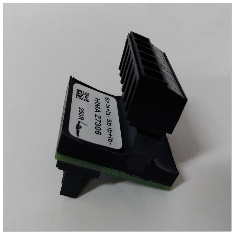
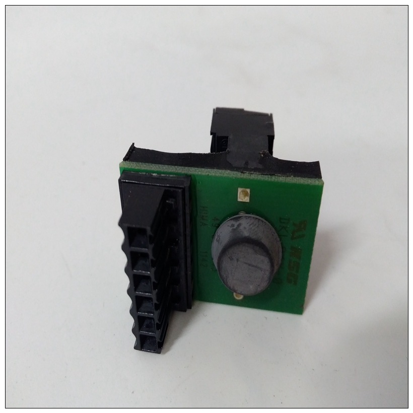
HIMA Z7306端子模块,Z7306使用手册
❏ SCSI接口(通过P2适配器)用于连接到两个内部和外部设备
❏ 插座安装的SCSI端接电阻器,用于电缆末端或中间电缆配置
❏ 调制解调器连接规定
❏ SCSI终端电源的绿色LED;以太网黄色LED收发器功率P2适配器板的功能包括:
❏ 一个50针连接器,用于SCSI布线至MVME712M和/或其他SCSI设备❏ 插座安装的SCSI端接电阻器,用于电缆末端或中间电缆配置
")
HIMA Z7306端子模块❏ 由+5VDC电源开发的熔断SCSI终端电源接头P2处
❏ 一个64针DIN连接器,用于连接EIA-232-D、并行、SCSI、,和以太网信号传输至MVME712M串行端口1-4 DCE/DTE配置串行端口1到4可配置为调制解调器(DCE)进行连接连接到终端,或作为连接到调制解调器的终端(DTE)。这个MVME712M附带为DTE配置的串行端口活动串行端口DCE/DTE配置由以下步骤完成:在每个端口的两个收割台之一上定位跳线。下表列出串行端口及其相应的跳线头。接下来的六幅图说明了MVME2603/2604基板和带互连和跳线的MVME712M过渡模块每个串行端口上的DCE/DTE配置设置。串行端口4时钟配置端口4可以通过J15(图1-4)配置为使用TrxC4和RtxC4信号线。部分配置使用收割台J16、J17和
MVME2603/2604上的J20(图1-9和图1-10)。P2适配器准备MVME712M P2适配器的准备包括拆除或安装SCSI端接电阻器。图1-11说明了电阻器、保险丝和接头的位置。
有关准备过渡模块和P2适配器,请参阅MVME712M的用户手册(中列出附录D,相关文件)
❏ An SCSI interface (via P2 adapter) for connection to both internal
and external devices
❏ Socket-mounted SCSI terminating resistors for end-of-cable or
middle-of-cable configurations
❏ Provision for modem connection
❏ Green LED for SCSI terminator power; yellow LED for Ethernet
transceiver power
The features of the P2 adapter board include:
❏ A 50-pin connector for SCSI cabling to the MVME712M and/or to
other SCSI devices❏ Socket-mounted SCSI terminating resistors for end-of-cable or
middle-of-cable configurations
❏ Fused SCSI terminator power developed from the +5VDC present
at connector P2
❏ A 64-pin DIN connector to interface the EIA-232-D, parallel, SCSI,
and Ethernet signals to the MVME712MSerial Ports 1-4 DCE/DTE Configuration
Serial ports 1 through 4 are configurable as modems (DCE) for connection
to terminals, or as terminals (DTE) for connection to modems. The
MVME712M is shipped with the serial ports configured for DTE
operation. Serial port DCE/DTE configuration is accomplished by
positioning jumpers on one of two headers per port. The following table
lists the serial ports with their corresponding jumper headers.
The next six figures illustrate the MVME2603/2604 base board and
MVME712M transition module with the interconnections and jumper
settings for DCE/DTE configuration on each serial port.
Serial Port 4 Clock Configuration
Port 4 can be configured via J15 (Figure 1-4)to use the TrxC4 and RtxC4
signal lines. Part of the configuration is done with headers J16, J17, and
J20 on the MVME2603/2604 (Figure 1-9 and Figure 1-10).P2 Adapter Preparation
Preparation of the P2 adapter for the MVME712M consists of removing or
installing the SCSI terminating resistors. Figure 1-11 illustrates the
location of the resistors, fuse, and connectors.
For further information on the preparation of the transition module and the
P2 adapter, refer to the user’s manual for the MVME712M (listed in
Appendix D, Related Documentation) as necessary

