


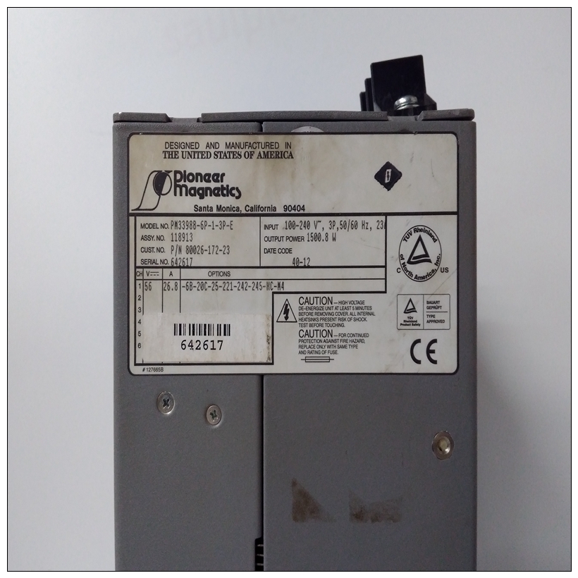
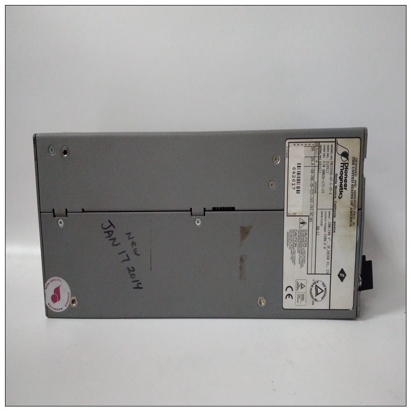
PM3398B-6P-1-3P-E工控模块,PIONEER MAGNETICS中文PDF使用手册
作为参数的地址许多命令使用ADDR作为参数。197Bug接受的语法是类似于单行汇编程序所接受的。所有控件寻址允许模式。还提供了“地址+偏移寄存器”模式。地址格式
地址是以十六进制数字输入的,地址或范围的起始地址可以是由形式为^S、^S、^U或^U的后缀限定,其中S或S定义管理器地址空间,U或U定义用户地址空间。默认值,如果未指定限定符,则为Supervisor。
")
PM3398B-6P-1-3P-E工控模块一旦输入了限定符,它对为输入的所有地址都有效该命令序列,直到重新输入197Bug或另一个限定符假如偏移寄存器八个称为偏移寄存器的伪寄存器(Z0-Z7)用于简化可重定位和位置独立模块的调试。列表文件在这些类型的程序中,通常从一个地址(通常为0)开始,该地址不是加载地址的位置,因此在在加载的程序中列出地址。偏移寄存器解决了这个问题通过考虑此差异并强制显示相对地址+偏移量格式的地址。偏移寄存器可调范围,甚至可能有重叠的范围。每个偏移的范围寄存器由两个地址设置:基址和顶址。指定底部和顶部偏移寄存器的地址设置其范围。如果地址掉了在两个或多个偏移寄存器的范围内,产生最小偏移的是被选中的。端口号一些197Bug命令允许用户选择要使用的端口输入或输出。可用于这些的有效端口号命令包括:1.MVME197LE EIA-232-D调试(终端端口0或00)(上的端口1)MVME197LE P2连接器)。有时被称为“控制台端口”,它是默认情况下用于交互式用户输入/输出。2.MVME197LE EIA-232-D(终端端口1或01)(上的端口2)MVME197LE P2连接器)。有时也称为“主机端口”,这是下载、上载、并发模式和透明模式。注意:这些逻辑端口号(0和1)显示在MVME197模块的引脚为“串行端口1”和分别为“串行端口2”。身体上,他们都是一部分接头P2的。
Address as a Parameter
Many commands use ADDR as a parameter. The syntax accepted by 197Bug is
similar to the one accepted by the one-line assembler. All control addressing
modes are allowed. An “address + offset register” mode is also provided.
Address Formats
Addresses are entered as a hexadecimal number, e.g., 20000 would correspond
to address $00020000. The address, or starting address of a range, can be
qualified by a suffix of the form ^S, ^s, ^U, or ^u, where S or s defines
Supervisor address space, and U or u defines user address space. The default,
when the qualifier is not specified, is Supervisor.
Once a qualifier has been entered, it remains valid for all addresses entered for
that command sequence, until the 197Bug is re-entered or another qualifier is
provided.Offset Registers
Eight pseudo-registers (Z0-Z7) called offset registers are used to simplify the
debugging of relocatable and position-independent modules. The listing files
in these types of programs usually start at an address (normally 0) that is not
the one at which they are loaded, so it is harder to correlate addresses in the
listing with addresses in the loaded program. The offset registers solve this
problem by taking into account this difference and forcing the display of
addresses in a relative address+offset format. Offset registers have adjustable
ranges and may even have overlapping ranges. The range for each offset
register is set by two addresses: base and top. Specifying the base and top
addresses for an offset register sets its range. In the event that an address falls
in two or more offset registers' ranges, the one that yields the least offset is
chosen.Port Numbers
Some 197Bug commands give the user the option to choose the port to be used
to input or output. Valid port numbers which may be used for these
commands are:
1. MVME197LE EIA-232-D Debug (Terminal Port 0 or 00) (PORT 1 on the
MVME197LE P2 connector). Sometimes known as the “console port”, it is
used for interactive user input/output by default.
2. MVME197LE EIA-232-D (Terminal Port 1 or 01) (PORT 2 on the
MVME197LE P2 connector). Sometimes known as the “host port”, this is
the default for downloading, uploading, concurrent mode, and
transparent modes.
Note These logical port numbers (0 and 1) are shown in the
pinouts of the MVME197 module as “SERIAL PORT 1” and
“SERIAL PORT 2”, respectively. Physically, they are all part
of connector P2.

