


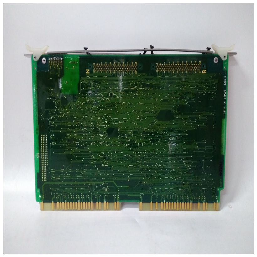
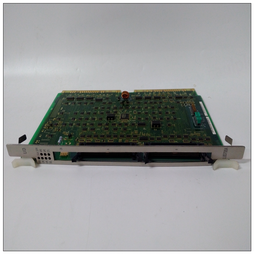
LUD700A卡件,HITACHI使用手册
远程处理器放置在MPCR中的ASCII G表示Go请求直接传输类型。MPCR中的ASCII B表示在转移控制之前,应设置断点(与GO一样命令)。在任一序列中,在MPCR中放置一个E,以指示执行是就在控制权移交给RAM之前。(任何远程处理器都可以检查MPCR内容。)
如果在双端口RAM中执行的代码要重新进入调试监视器,使用函数$0063(SYSCALL.RETURN)的陷阱#496调用返回控制以新的显示提示显示到监视器。注意,每次调试
监视器返回提示,将R移到MPCR中以指示控制可以再次转移到指定的RAM位置。
")
LUD700A卡件R方法远程处理器可以在本地MVME197LE中启动程序执行通过使用VMEchip2全局命令发出远程GO命令,实现双端口RAM控制和状态寄存器(GCSR)。远程处理器放置通用寄存器0和1(GPCSR0)中的MVME197LE执行地址和GPCSR1)。然后,远程处理器设置VMEchip2的位8(SIG0)LM/SIG寄存器。这导致MVME197LE安装断点和开始执行。结果与MPCR方法相同(带有状态代B) 如前一节所述。GCSR寄存器在VMEbus短输入/输出空间中访问。每个通用目的寄存器的宽度为两个字节,位于偶数地址。将目的寄存器编号0的偏移量为8美元(本地外围总线)或4美元(VMEbus)从GCSR寄存器开始。本地外围总线基础GCSR的地址为$FFF40100。GCSR的VMEbus基址取决于编程的组选择值和电路板选择值MVME197LE的本地控制和状态寄存器(LCSR)。这个执行地址是通过读取中的GCSR通用寄存器形成的以下方式:197Bug包中包含一整套硬件诊断用于MVME197LE的测试和故障排除(请参阅MVME197单板计算机诊断固件用户手册)。整齐要使用诊断,用户必须将目录切换到诊断目录如果在调试器目录中,用户可以切换到诊断通过输入调试器命令切换目录(SD)。这个应出现诊断提示(“197 Diag>”)。参考MVME197单Board Computer Diagnostic Firmware User’s Manual for Computer Diagnostic Firmware的完整说明可用的诊断例程以及如何调用它们的说明。请注意,某些诊断依赖于仅在特殊重启模式。请参阅特定诊断的文档正确的模式。
An ASCII G placed in the MPCR by a remote processor indicates that the Go
Direct type of transfer is requested. An ASCII B in the MPCR indicates that
breakpoints are to be armed before control is transferred (as with the GO
command).
In either sequence, an E is placed in the MPCR to indicate that execution is
underway just before control is passed to RAM. (Any remote processor could
examine the MPCR contents.)
If the code being executed in dual-port RAM is to reenter the debug monitor,
a TRAP #496 call using function $0063 (SYSCALL .RETURN) returns control
to the monitor with a new display prompt. Note that every time the debug
monitor returns to the prompt, an R is moved into the MPCR to indicate that
control can be transferred once again to a specified RAM location.R Method
A remote processor can initiate program execution in the local MVME197LE
dual-port RAM by issuing a remote GO command using the VMEchip2 Global
Control and Status Register (GCSR). The remote processor places the
MVME197LE execution address in general purpose registers 0 and 1 (GPCSR0
and GPCSR1). The remote processor then sets bit 8 (SIG0) of the VMEchip2
LM/SIG register. This causes the MVME197LE to install breakpoints and
begin execution. The result is identical to the MPCR method (with status code
B) described in the previous section.
The GCSR registers are accessed in the VMEbus short I/O space. Each general
purpose register is two bytes wide, occurring at an even address. The general
purpose register number 0 is at an offset of $8 (local peripheral bus) or $4
(VMEbus) from the start of the GCSR registers. The local peripheral bus base
address for the GCSR is $FFF40100. The VMEbus base address for the GCSR
depends on the group select value and the board select value programmed in
the Local Control and Status Registers (LCSR) of the MVME197LE. The
execution address is formed by reading the GCSR general purpose registers in
the following manner:Included in the 197Bug package is a complete set of hardware diagnostics
intended for testing and troubleshooting of the MVME197LE (refer to the
MVME197 Single Board Computer Diagnostic Firmware User’s Manual). In order
to use the diagnostics, the user must switch directories to the diagnostic
directory. If in the debugger directory, the user can switch to the diagnostic
directory by entering the debugger command Switch Directories (SD). The
diagnostic prompt (“197-Diag>”) should appear. Refer to the MVME197 Single
Board Computer Diagnostic Firmware User’s Manual for complete descriptions of
the diagnostic routines available and instructions on how to invoke them.
Note that some diagnostics depend on restart defaults that are set up only in a
particular restart mode. Refer to the documentation on a particular diagnostic
for the correct mode

