


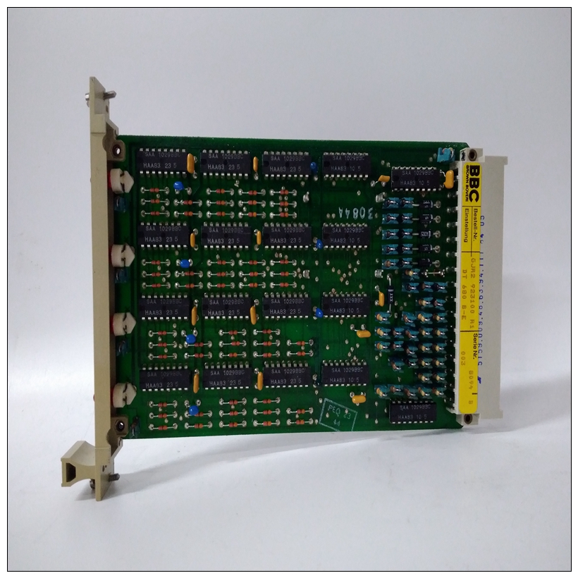
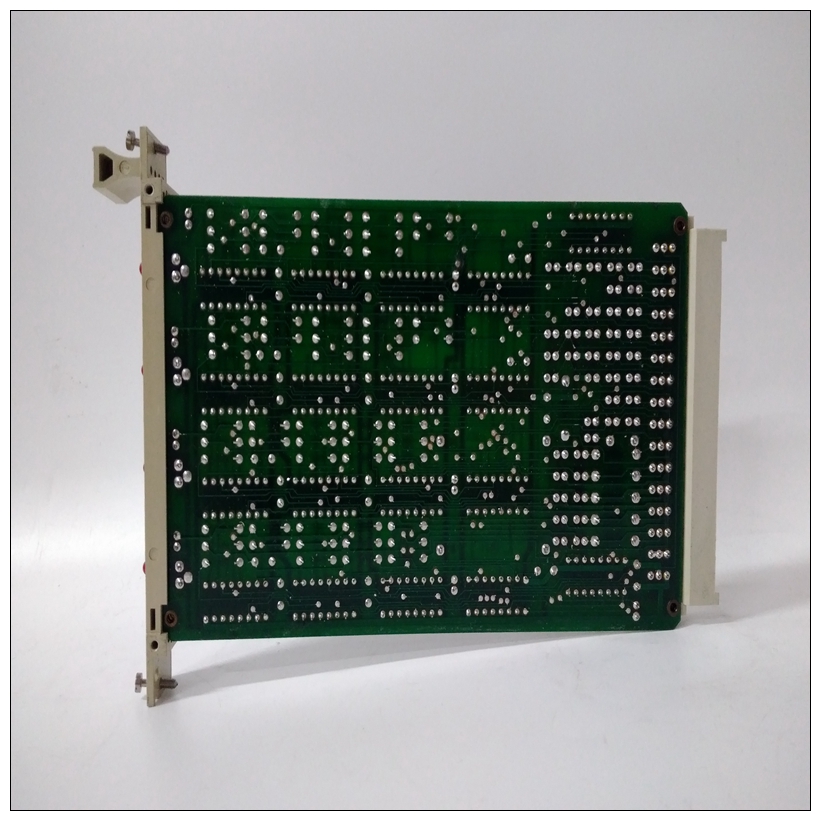

DT680E固定模块,ABB参数说明
与基于M68000的固件的比较那些使用过摩托罗拉一个或多个其他调试的用户软件包将发现197Bug非常相似,在适当考虑了M68000和M88000 CPU架构之间的架构差异。这些主要体现在指令助记符和寻址中汇编程序/反汇编程序的模式,以及使用寄存器代替用于向陷阱#496处理程序传递参数或从陷阱#496处理程序传递参数的堆栈。一些还努力使交互式命令更加一致。
")
DT680E固定模块例如,命令和参数之间的分隔符现在可能是逗号或空格可以互换。197Bug实施MVME197BUG主要用“C”编程语言编写,提供可移植性和可维护性的好处。必要时,汇编程序以单独编译的模块的形式使用只包含汇编代码-不使用混合语言模块。实际上,197Bug包含在板载闪存中。可执行文件每次通电或重置固件条目时对代码进行校验和,并且结果(包括闪存中包含的预计算校验和内存),测试预期为零。因此,提醒用户除非采取重新校验和预防措施,否则修改闪存。安装和启动即使MVME197Bug闪存设备安装在MVME197LE模块,用于197Bug与MVME197LE一起正常工作,遵循此设置程序。通电时插入或卸下模块可能损坏模块组件。1、关闭所有设备电源。请参阅硬件准备和本手册中用于选择配置开关的安装章节用户特定应用程序所需的设置。2.有关详细信息,请参阅用户特定机箱或系统的设置程序有关MVME197LE安装的详细信息。3.将用作197Bug系统控制台的终端连接到背板连接器上串行端口1处的默认调试EIA-232-D端口P2通过MVME712X过渡模块。参考MVME197LE,MVME197DP和MVME197SP单板机程序员一些可能的连接图的参考指南。设置终端具体如下:
–每个字符8位–每个字符一个停止位–奇偶校验禁用(无奇偶校验)–波特率9600波特(MVME197LE端口的默认波特率为通电)
Comparison With M68000-Based Firmware
Those users who have used one or more of Motorola's other debugging
packages will find 197Bug very similar, after making due allowances for the
architectural differences between the M68000 and M88000 CPU architectures.
These are primarily reflected in the instruction mnemonics and addressing
modes of the assembler/disassembler, and in the use of registers instead of the
stack for the passing of arguments to or from the TRAP #496 handler. Some
effort has also been made to make the interactive commands more consistent.
For example, delimiters between commands and arguments may now be
commas or spaces interchangeably.
197Bug Implementation
MVME197BUG is written largely in the “C” programming language,
providing benefits of portability and maintainability. Where necessary,
assembler has been used in the form of separately compiled modules
containing only assembler code - no mixed language modules are used.
Physically, 197Bug is contained in the onboard flash memory. The executable
code is checksummed at every power-on or reset firmware entry, and the
result (which includes a pre-calculated checksum contained in the flash
memory), is tested for an expected zero. Thus, users are cautioned against
modification of the flash memory unless re-checksum precautions are taken.
Installation and Start-up
Even though the MVME197Bug flash memory devices are installed on the
MVME197LE module, for 197Bug to operate properly with the MVME197LE,
follow this set-up procedure.Inserting or removing modules while power is applied
could damage module components.
1. Turn all equipment power OFF. Refer to the Hardware Preparation and
Installation chapter in this manual for selecting the configuration switch
settings required for the user’s particular application.
2. Refer to the set-up procedure for the user’s particular chassis or system for
details concerning the installation of the MVME197LE.
3. Connect the terminal which is to be used as the 197Bug system console to
the default debug EIA-232-D port at serial port 1 on backplane connector
P2 through an MVME712X transition module. Refer to the MVME197LE,
MVME197DP, and MVME197SP Single Board Computers Programmer’s
Reference Guide for some possible connection diagrams. Set up the terminal
as follows:
– eight bits per character
– one stop bit per character
– parity disabled (no parity)
– baud rate 9600 baud (default baud rate of the MVME197LE ports at
power-up)

