


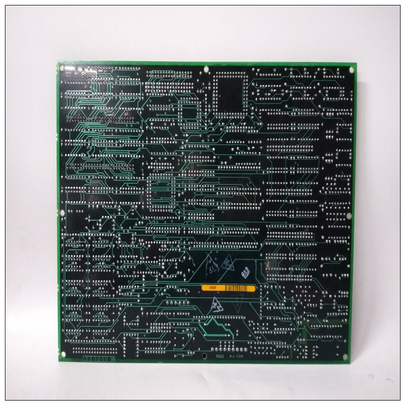
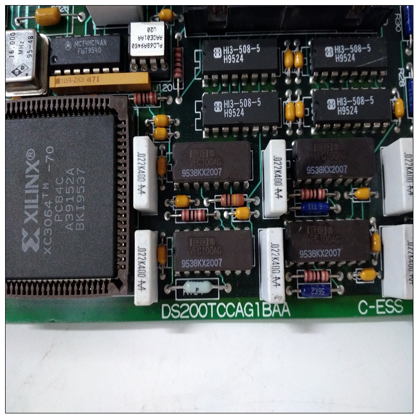
DS200TCCAG1BAA通用卡件,GE中文PDF说明书在线阅读
配置交换机上的开关、连接器和LED指示灯的位置MVME197LE如图2-1所示。MVME197LE已出厂已测试,出厂时附带出厂开关设置,如中所述
以下章节。MVME197LE使用其所需和工厂安装的调试监视器MVME197Bug(197Bug)以及这些工厂开关运行背景配置开关S1:一般信息开关S1由九个双向开关段组成。以下内容
图显示了开关S1的出厂配置。位值为当开关断开时,读数为1,当开关断开时,读数为零打开(关闭)。开关S1的默认值如下所示。
")
DS200TCCAG1BAA通用卡件MVME197LE上的八条通用输入线(GPI0-GPI7)可能
配置可选开关段S1-1至S1-8。这些开关可以在VMEchip2 LCSR中作为寄存器读取(在$FFF40088处)。参考MVME197LE、MVME197DP和MVME197SP中的VMEchip2章节单板计算机GPI0线路状态程序员参考指南通过GPI7。工厂配置为通用输入线禁用(打开)。MVME197LE可以作为系统控制器。系统控制器通过配置可选开关段启用或禁用功能S1-9。当MVME197LE是系统控制器时,SCON LED为已打开。VMEchip2可以配置为系统控制器,如下所示:如下图所示。出厂配置使用系统控制器开关已启用(关闭)。串行端口4可以配置为使用RTXC4和TRXC4信号线。MVME197LE上的开关段S6-1和S6-2将串行端口4配置为分别驱动或接收TRXC4和RTXC4。出厂配置为串行端口4设置为接收两个信号(打开)。时钟线的其余配置通过使用MVME712M转换上的串行端口4时钟配置选择标头单元参考MVME712M过渡模块和P2适配器板该标题配置的用户手册。
Configuration Switches
The location of the switches, connectors, and LED indicators on the
MVME197LE is illustrated in Figure 2-1. The MVME197LE has been factory
tested and is shipped with factory switch settings that are described in the
following sections. The MVME197LE operates with its required and factoryinstalled Debug Monitor, MVME197Bug (197Bug), with these factory switch
setting.
Configuration Switch S1: General Information
Switch S1 is a bank of nine two-way switch segments. The following
illustration shows the factory configuration of switch S1. The bit values are
read as a one when the switch is OFF (open), and as a zero when the switch is
ON (closed). The default value for switch S1 is shown below.The eight General Purpose Input lines (GPI0-GPI7) on the MVME197LE may
be configured with selectable switch segments S1-1 through S1-8. These
switches can be read as a register (at $FFF40088) in the VMEchip2 LCSR. Refer
to the VMEchip2 chapter in the MVME197LE, MVME197DP, and MVME197SP
Single Board Computers Programmer’s Reference Guide for the status of lines GPI0
through GPI7. Factory configuration is with the general purposes input lines
disabled (open).The MVME197LE can be the system controller. The system controller
function is enabled or disabled by configuring selectable switch segment
S1-9. When the MVME197LE is the system controller, the SCON LED is
turned ON. The VMEchip2 may be configured as a system controller as
illustrated below. Factory configuration is with the system controller
switch enabled (closed).Serial port 4 can be configured to use clock signals provided by the RTXC4 and
TRXC4 signal lines. Switch segments S6-1 and S6-2 on the MVME197LE
configures serial port 4 to drive or receive TRXC4 and RTXC4, respectively.
Factory configuration is with serial port 4 set to receive both signals (open).
The remaining configuration of the clock lines is accomplished by using the
Serial Port 4 Clock Configuration Select header on the MVME712M transition
module. Refer to the MVME712M Transition Module and P2 Adapter Board
User’s Manual for configuration of that header.

