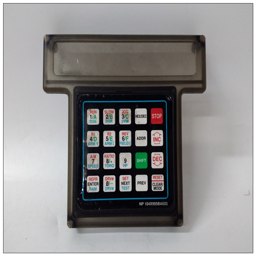
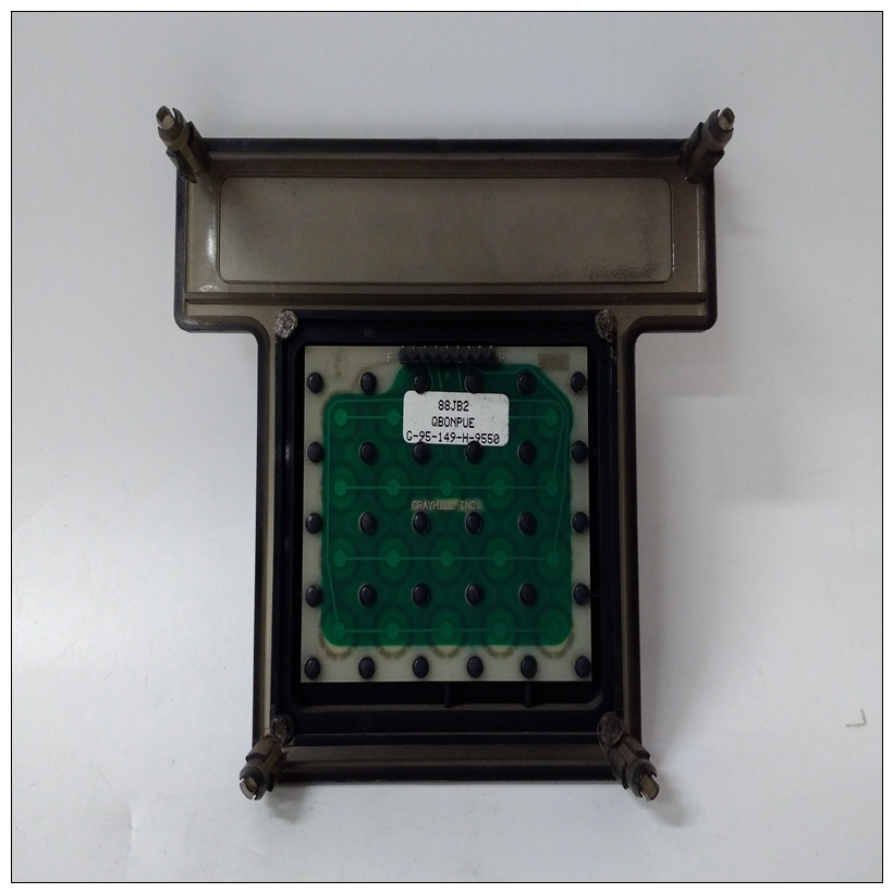
G-95-149-H-9550通用电气模块,GE使用配置手册
当装置连接到不同的电气设备时插座,接地电位可能有几伏的差异。
如果每个设备的针脚1通过电缆相互连接,可能会产生几安培的电流。这种情况可能不会仅对典型电缆中的小导线有危险,但可能还会产生电噪声,导致数据传输错误。
这就是为什么图E-1没有显示针1的连接。通常情况下,针脚7只应连接到机箱一点接地;如果多个端子与一个端子一起使用计算机,这一点的逻辑位置是在计算机上。

G-95-149-H-9550通用电气模块这个端子之间不应存在逻辑接地连接返回和机箱。介绍本章介绍MVME197LE的板级硬件功能单板计算机。本章包括董事会层面的概述和本简介中列出的功能,然后是更详细的硬件功能描述。前面板开关和指示灯包括在详细的硬件功能描述。本章以一些通用内存映射。MVME197LE模块中的所有可编程寄存器位于ASIC中(特定于应用的集成电路)MVME197LE、MVME197DP和MVME197SP单板计算机程序员参考指南。概述MVME197LE模块是基于MC88110 RISC微处理器。MVME197LE具有32/64MB的DRAM,1MB闪存,8KB静态RAM(带备用电池),每天一次时钟(带备用电池)、以太网收发器接口、四个串行端口带EIA-232-D接口,六个滴答定时器,一个看门狗定时器,128KB启动ROM,一个带有DMA(直接内存访问)的SCSI总线接口,一个Centronics打印机端口,A16/A24/A32/D8/D16/D32 VMEbus主/从接口和VMEbus系统控制器。输入/输出(I/O)信号通过MVME197LE的背板布线接头P2。P2适配器板或LCP2适配器板路由信号并从连接器P2接地至MVME712系列过渡模块。这个MVME197LE支持MVME712M、MVME712A、MVME712AM和MVME712B过渡板(此处称为MVME712X,除非单独规定)。MVME197LE还支持MVME712-12和MVME712-13(除非另有规定,否则称为MVME712-XX)。这些转换板提供配置头、串行端口驱动程序和输入/输出设备的行业标准连接器。MVME197LE模块有八个ASIC(如下所述顺序:总线开关、DCAM、ECDM、PCC2和VME2)。
The problem is that when units are connected to different electrical
outlets, there may be several volts of difference in ground potential.
If pin 1 of each device is interconnected with the others via cable,
several amperes of current could result. This condition may not
only be dangerous for the small wires in a typical cable, but may
also produce electrical noise that causes errors in data transmission.
That is why Figure E-1 shows no connection for pin 1.
Normally, pin 7 should only be connected to the CHASSIS
GROUND at one point; if several terminals are used with one
computer, the logical place for that point is at the computer. The
terminals should not have a connection between the logic ground
return and the chassis.Introduction
This chapter describes the board level hardware features of the MVME197LE
Single Board Computer. The chapter is organized with a board level overview
and features listed in this introduction, followed by a more detailed hardware
functional description. Front panel switches and indicators are included in the
detailed hardware functional description. This chapter closes with some
general memory maps.
All programmable registers in the MVME197LE module reside in ASICs
(Application-Specific Integrated Circuits) that are covered in the
MVME197LE, MVME197DP, and MVME197SP Single Board Computers
Programmer’s Reference Guide.
Overview
The MVME197LE module is a double-high VMEmodule based on the
MC88110 RISC microprocessor. The MVME197LE has 32/64MB of DRAM,
1MB of flash memory, 8KB of static RAM (with battery backup), a time of day
clock (with battery backup), an Ethernet transceiver interface, four serial ports
with EIA-232-D interface, six tick timers, a watchdog timer, 128KB of BOOT
ROM, a SCSI bus interface with DMA (Direct Memory Access), a Centronics
printer port, an A16/A24/A32/D8/D16/D32 VMEbus master/slave
interface, and a VMEbus system controller.
Input/Output (I/O) signals are routed through the MVME197LE’s backplane
connector P2. A P2 Adapter Board or LCP2 Adapter board routes the signals
and grounds from connector P2 to an MVME712 series transition module. The
MVME197LE supports the MVME712M, MVME712A, MVME712AM, and
MVME712B transition boards (referred to here as the MVME712X, unless
separately specified). The MVME197LE also supports the MVME712-12 and
MVME712-13 (referred to as the MVME712-XX, unless separately specified).
These transition boards provide configuration headers, serial port drivers, and
industry standard connectors for the I/O devices.
The MVME197LE modules have eight ASICs (described in the following
order: BusSwitch, DCAM, ECDM, PCC2, and VME2).


