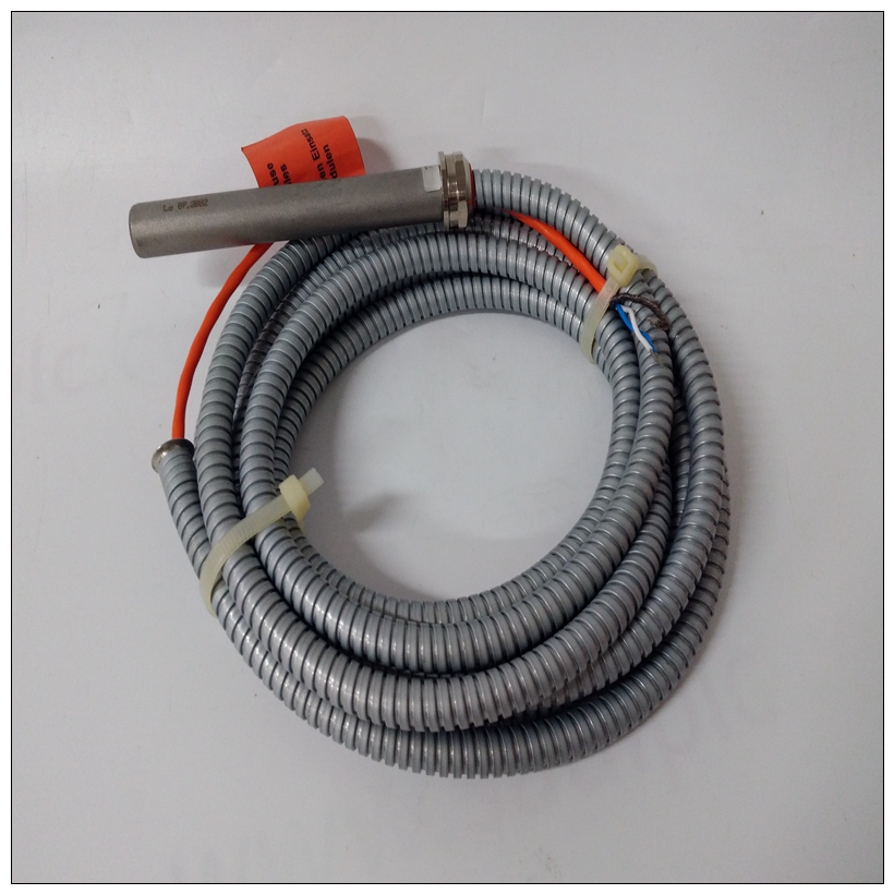
EPRO PR937620前置电缆,PR937620使用数据
设备连接单板计算机中有一些连接图程序员参考指南。
MVME712X转换模块和P2适配器板连接MVME187的外围设备如表3-10所示。控制台终端、主机系统、调制解调器或串行打印机上的EIA-232-D串行端口过渡模块上的并行打印机Centronics打印机端口过渡模块可选内部调制解调器(请参阅过渡用户手册详细信息模块)

EPRO PR937620前置电缆可选调制解调器端口,替换串行端口过渡模块上的端口2内部SCSI驱动器适配器板和转换模块上的外部SCSI驱动器SCSI接口连接器过渡模块以太网连接过渡模块上的以太网端口在过渡模块上设置跳线模块并安装SCSIP2上的终端(如需要)适配器板。
用户手册中的模块准备过渡模块手册和适配器板SCSI总线终端,第3-29页2连接并安装MVME712X前部的过渡模块或机箱后部。
用户手册中的安装说明过渡模块手册和适配器板3连接并安装❏ 位于上的P2接头MVME187处的背板狭槽用户手册中的安装说明过渡模块手册和适配器板❏ 来自P2的SCSI电缆
适配器板至MVME712X过渡模块和内部SCSI设备。用户手册中的模块准备过渡模块手册适配器板和SCSI总线第3-29页连接外围设备上的终端MVME187与(可选)终端或其他外围设备配套在EIA-232-D串行端口(标记为串行端口1、2、3和4在MVME712X转换模块上)、并行端口、SCSI端口、,和LAN以太网端口,如第3-22页图3-3所示。
注:MVME712X未提供一些电缆模块,因此由使用者(摩托罗拉建议使用屏蔽电缆所有与外围设备的连接,以尽量减少辐射。)
Equipment Connections
Some connection diagrams are in the Single Board Computer
Programmer's Reference Guide.
The MVME712X transition modules and P2 adapter boards connect
peripheral equipment to the MVME187 as shown in Table 3-10.Console terminals, host computer
systems, modems, or serial printers
EIA-232-D serial ports on the
transition module
Parallel printers Centronics printer port on the
transition module
Optional internal modems (see the
user’s manual for your transition
module for details)
Optional modem port, replacing serial
port 2 on the transition module
Internal SCSI drives Adapter board and transition module
External SCSI drives SCSI interface connector on the
transition module
Ethernet connections Ethernet port on the transition moduleSet jumpers on the transition
module(s) and install SCSI
terminators (if needed) on the P2
adapter board.
Module Preparation in the user’s
manual for your transition module
and adapter board, and
SCSI Bus Termination on page 3-29
2 Connect and install the MVME712X
transition module in the front or the
rear of the chassis.
Installation Instructions in the user’s
manual for your transition module
and adapter board
3 Connect and install
❏ The P2 adapter board at the
P2 connector on the
backplane at the MVME187
slot.
Installation Instructions in the user’s
manual for your transition module
and adapter board
❏ SCSI cable(s) from the P2
adapter board to the
MVME712X transition
module and internal SCSI
devices.
Module Preparation in the user’s
manual for your transition module
and adapter board, and SCSI Bus
Termination on page 3-29Connecting Peripherals
The MVME187 mates with (optional) terminals or other peripherals
at the EIA-232-D serial ports (marked SERIAL PORTS 1, 2, 3, and 4
on the MVME712X transition module), parallel port, SCSI ports,
and LAN Ethernet port, as shown in Figure 3-3 on page 3-22.
Note Some cable(s) are not provided with the MVME712X
module(s), and therefore are made or provided by the
user. (Motorola recommends using shielded cables for
all connections to peripherals to minimize radiation.)


