


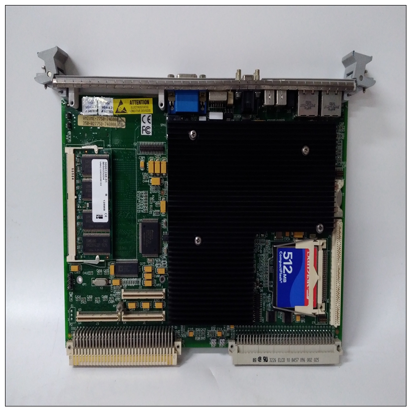
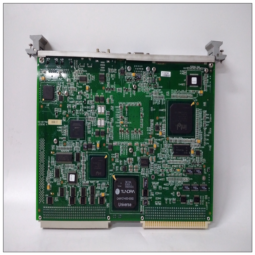
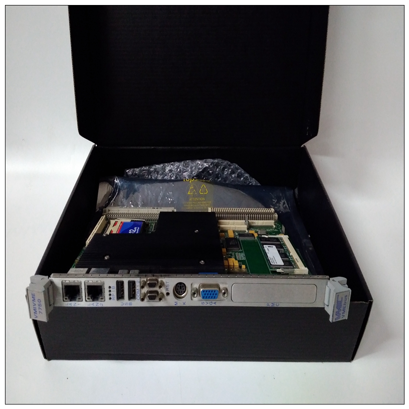
VMIVME-7750-746000通用电气卡件,GE数据库
根据本节中的跳线设置,安装/拆除收割台上的跳线根据您的具体应用需要。
❏ 收割台J1上的跳线影响跳线中列出的操作设置。默认情况是安装了所有八个跳线
❏ 收割台J2上安装/拆除的跳线启用/禁用MVME187的系统控制器功能。
❏ 在收割台J7和J8上安装跳线,以将串行端口4配置为使用TRXC4和RTXC4信号线提供的时钟信号。2根据MVME712X配置适配器和转换模块过渡模块用户手册。3确保EPROM设备正确安装在其插座中。
")
VMIVME-7750-746000通用电气卡件❏ 出厂配置中安装了两个EPROM,用于MVME187Bug调试监视器,位于套接字XU1和XU2中。现在MVME187模块已准备好安装,请准备系统机箱并确定插槽分配(对于外围设备,转换模块等)如下:在通电时插入或卸下模块可能导致模块组件损坏。
可能导致死亡的危险电压包括:存在于该设备中。在以下情况下,请格外小心:处理、测试和调整关闭底盘和外围设备的所有电源。2断开交流电源电缆与电源的连接。
3按照用户手册中的说明卸下机箱盖特定底盘或系统。
4.从正面相应的卡槽中卸下填充板和机箱后部(如果机箱具有后卡固定框架)。如果MVME187配置为系统控制器:如果未配置为系统
控制器:它必须安装在最左侧的卡槽(槽1)至正确启动总线授权菊花链和有适当的IACK菊花链的操作驾驶员它可以安装在任何双高未使用的卡槽中。安装硬件本节涵盖
❏ 将MVME187安装到VME机箱中
❏ 过渡模块和适配器的概述和安装
❏ 控制台等外围设备的连接终端、可选SCSI驱动器和串行或并行打印机
Install/remove jumpers on headers according to the Jumper Settings in this
chapter and as required for your particular application.
❏ Jumpers on header J1 affect 187Bug operation as listed in Jumper
Settings. The default condition is with all eight jumpers installed
❏ A jumper installed/removed on header J2 enables/disables the
system controller function of the MVME187.
❏ Install jumpers on headers J7 and J8 to configure serial port 4 to
use clock signals provided by the TRXC4 and RTXC4 signal lines.
2 Configure adapters and transition modules according to the MVME712X
transition module user's manuals.
3 Ensure that EPROM devices are properly installed in their sockets.
❏ Factory configuration is with two EPROMs installed for the
MVME187Bug debug monitor, in sockets XU1 and XU2. Now that the MVME187 module is ready for installation, prepare
the system chassis and determine slot assignments (for peripherals,
transition modules, etc.) as follows:Inserting or removing modules while power is applied
could result in damage to module components.
Dangerous voltages, capable of causing death, are
present in this equipment. Use extreme caution when
handling, testing, and adjustingTurn all power OFF to chassis and peripherals.
2 Disconnect AC power cable from source.
3 Remove chassis cover as shown in the user's manual for your
particular chassis or system.
4 Remove the filler panel(s) from the appropriate card slot(s) at the front
and rear of the chassis (if the chassis has a rear card cage).
If the MVME187 is configured as
system controller:
If it is not configured as system
controller:
It must be installed in the
left-most card slot (slot 1) to
correctly initiate the bus-grant
daisy-chain and to have proper
operation of the IACK-daisy-chain
driver.
It may be installed in any doubleheight unused card slot. Installing the Hardware
This section covers
❏ Installation of the MVME187 into a VME chassis
❏ Overview and installation of transition modules and adapter
boards
❏ Connection of peripheral equipment such as console
terminals, optional SCSI drives, and serial or parallel printers

