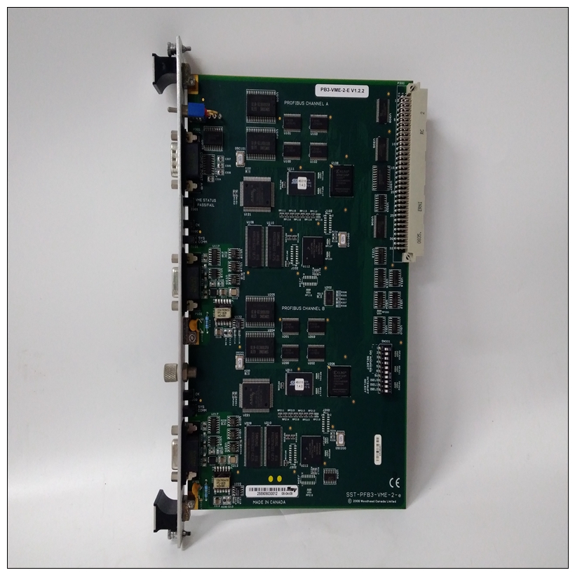
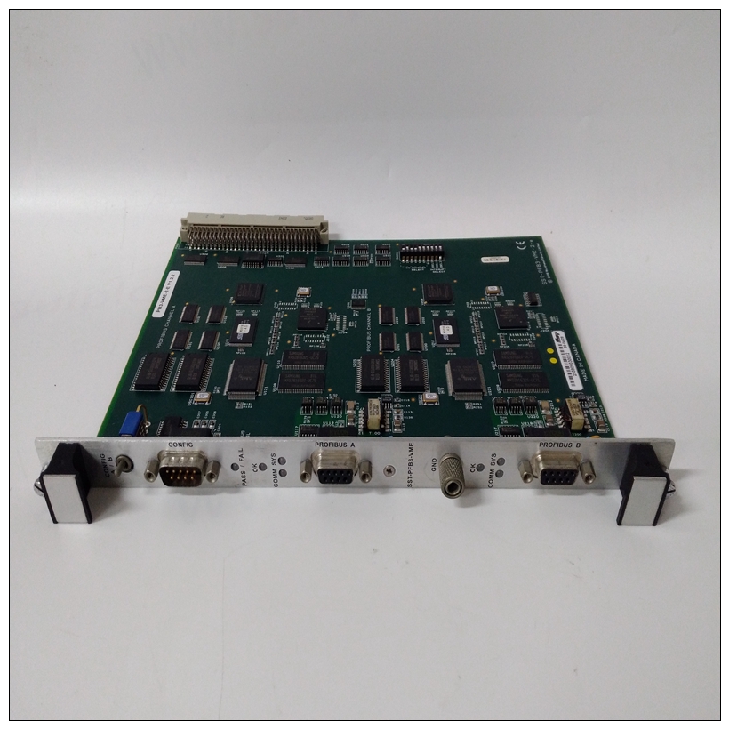
SST-PFB3-VME-2-E控制卡件,SST使用教程
1.板载EPROM在本地总线之后出现在$00000000-003FFFFF重置。EPROM显示为0,直到在
VMEchip2。ROM0位位于地址$FFF40030位20。这个在启用DRAM之前,必须在0禁用EPROM。VMEchip2和DRAM映射解码器被本地总线重置禁用。
2、该区域可由用户编程。建议使用如表所示。DRAM解码器在MEMC040或MCECC芯片中编程,并且本地到VMEbus解码器在VMEchip2中编程。
3、尺寸为近似值。
4.缓存抑制取决于映射区域中的设备。

SST-PFB3-VME-2-E控制卡件5、该区域未解码。如果访问这些位置,并且本地总线定时器启用,循环超时,并由TEA信号终止。1.有关寄存器位的完整描述,请参阅单板计算机程序员参考指南或数据表炸薯条
2.应使用字节读取来读取中断向量。这些位置可以中断未挂起时不响应。如果本地总线计时器为启用后,访问超时,并由TEA信号终止。
3.VMEchip2中LCSR的写入必须为32位。LCSR写入8或16位以TEA信号终止。对GCSR的写入可以是8位、16位或32位。对LCSR和GCSR的读取可以是8、16或32位。
4、该区域不返回确认信号。如果本地总线计时器为启用后,访问超时,并由TEA信号终止。
5.该区域确实返回确认信号。
6、尺寸为近似值。
7.82596CA的端口命令必须写入两个16位写入:上限第一个单词和第二个较低的单词。
8.CD2401从$FFF45200到$FFF45FFF重复出现。如果当地总线计时器启用,访问超时,并由TEA信号终止。VMEbus内存映射本节描述了由查看的本地资源映射VMEbus masters。从属、主和GCSR地址解码器由ENV命令提供。参考附录A。
VMEbus访问本地总线VMEchip2包括一个用于VMEbus到本地总线接口。地图解码器允许您编程起始和结束地址以及修饰符MVME187响应。
VMEbus短输入/输出内存映射VMEchip2包括一个用于GCSR。GCSR地图解码器允许您编程启动VMEbus短输入/输出空间中GCSR的地址
and the corresponding material kilogram will be automatically converted by PLC and imported into the system for application. The curve rate is obtained according to the weight of the test weight and the curve characteristics of the module (see the instruction description of the module curve rate for details).
PLC: the program adopts wplsoft2 35 ladder diagram software. It includes four main parts: system setting, analog quantity acquisition, automatic operation and manual operation. Scan the ladder diagram during operation, automatically jump and switch according to external instructions, and execute continuously.
Process control:
The console is equipped with manual / automatic transfer switch, emergency stop button, on-board quantity input button, automatic operation start button, system reset button, etc. For manual operation, each mechanism can be controlled independently.
On board quantity input button: each time you press it, the on-board quantity counter will automatically increase by one, and long press it to clear the data. You can also input the value directly through the touch screen. System reset button: clear the non power failure storage area register to return the system to standby state.
According to the construction requirements, input the corresponding data command through the man-machine interface, press the automatic operation start button, and the system will operate automatically and continuously. The operation process is divided into three stages: batching, feeding, mixing and concrete unloading.
1. Batching: the automatic operation start contact triggers the batching and metering of 4 aggregates, cement, chemicals and water. After the aggregate batching is completed, the system detects the hopper position. When the hopper is at the lower limit, the weighing belt is fed, and the weighing belt timer is started. When the time reaches, it will stop automatically. After the feeding of the weighing belt is completed, the system detects and waits: the host starts, the batching of cement, water and reagent is completed, and the hopper lifting is triggered when the mixing of the previous tank of concrete is completed and the concrete unloading door is closed. In this way, continuous material input into the host is effectively avoided. When the hopper is lifted, the PLC triggers the sampling of the historical data buffer, and records and saves the batching measurement value in columns according to the time and date.
2. Feeding: when the hopper is lifted in place, it will stop automatically. Put the aggregate into the main engine. The corresponding timer starts, and when the


