


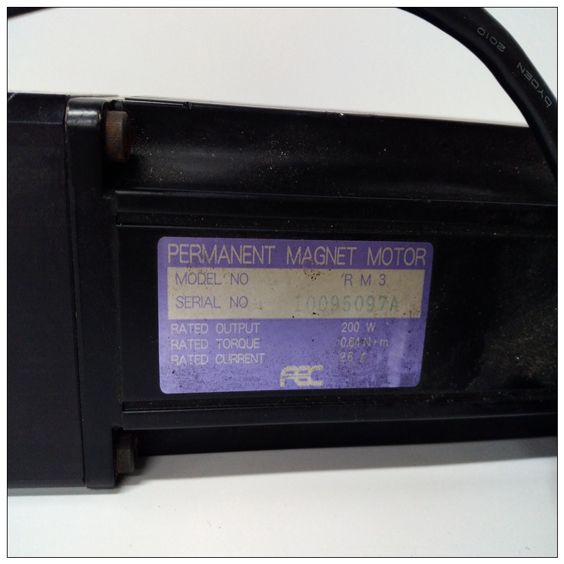
DDK NFT-801RM3-S拧紧机,NFT-801RM3-S电机
为了最大限度地减少电容负载和噪声,模块的所有现场连接应使用良好的电缆连接绞合屏蔽仪表电缆等级。屏蔽应连接至接地用户端子连接器块。接地连接提供对基板的访问(机架接地)可更好地抑制任何屏蔽漏电流引起的噪声。当模块的电源工作时,模块面板上的LED亮起。这个模块在现场接线和背板通过使用光学隔离。
")
DDK NFT-801RM3-S拧紧机该模块可以安装在5的任何输入/输出插槽中或90-30系列PLC系统中的10槽基板。如果用户提供的供应品不用于为模块供电,最多可以在一个模块中安装三个模拟电流输出模块基板。最大输出负载(电压模式)5 mA(2K欧姆最小电阻)(2000 pF最大电容)磁场和逻辑侧之间的隔离1500伏+5V电源的内部功耗为30 mA215 mA,来自隔离的+24 VDC背板电源或用户供应产品标准和通用规范见附录B。
1可根据图3-38所示的总模块电流计算电压输出选项上的允许负载。
2允许的用户供电取决于电流负载和环境温度,如图3-38所示。
3在存在严重射频干扰(IEC 801-3,10V/m)的情况下,精度可能会降低到µA(4至20mA)范围),µA(0至20 mA范围)以下两个图提供了将现场布线连接到模拟电路的信息电流输出模块。图3-40显示了使用输出所需的连接作为模拟电流输出。
To minimize thecapacitive loading and noise, all field connections to the module should be wired using a good
grade of twisted, shielded instrumentation cable. The shields should be connected to GND on
the user terminal connector block. The GND connection provides access to the baseplate
(frame ground) resulting in superior rejection of noise caused by any shield drain currents.
An LED on the module’s faceplate is ON when the module’s power supply is operating. The
module provides electrical isolation of externally generated noise between field wiring and the
backplane through use of optical isolation. This module can be installed in any I/O slot of a 5
or 10-slot baseplate in a Series 90-30 PLC system. If user provided supplies are not used to
power the module, a maximum of three Analog Current Output modules can be installed in a
baseplate.Maximum Output Loading (voltage mode) 5 mA (2K ohms minimum resistance) (2000 pF
maximum capacitance)
Isolation 1500 volts between field and logic side
Internal Power Consumption 30 mA from +5V supply
215 mA from Isolated +24 VDC backplane supply
or user supply
Refer to Appendix B for product standards and general specifications.
1 Allowable load on the voltage output option can be calculated from the total module current shown in Figure 3-38.
2 Allowable user supply is dependent on the current load and the ambient temperature as shown in Figure 3-38.
3 In the presence of severe RF interference (IEC 801-3, 10V/m), accuracy may be degraded to µA (4 to 20 mA
range), µA (0 to 20 mA range)The following two figures provide information for connecting field wiring to the Analog
Current Output module. Figure 3-40 shows the connections necessary for the outputs to be used
as analog current outputs.

