


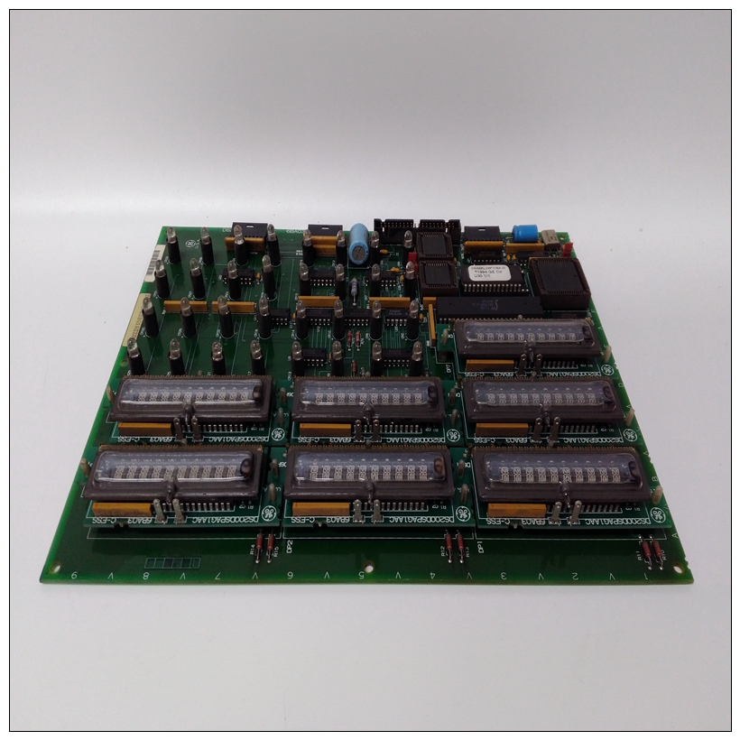
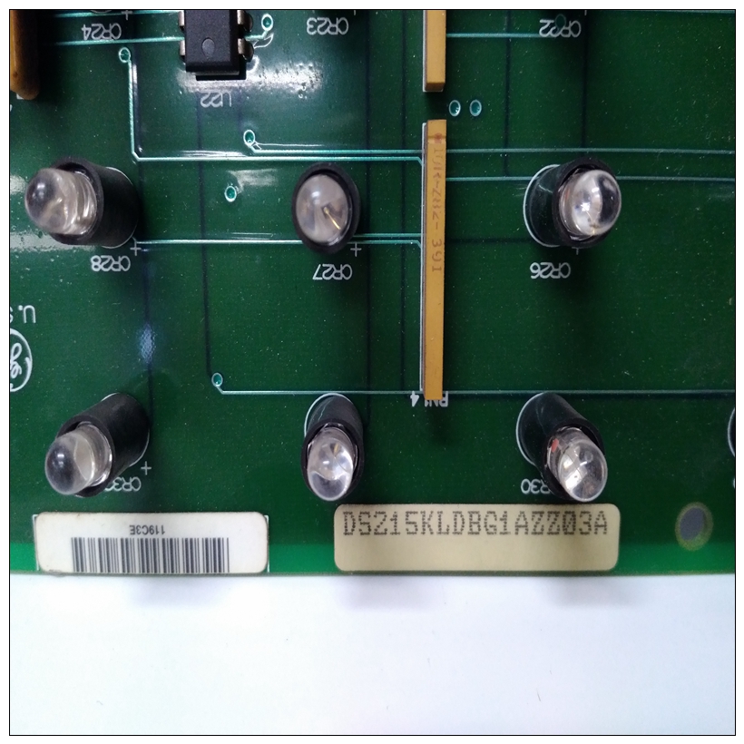
DS200KLDBG1ABC燃机卡件,DS200KLDBG1ABC怎么使用
90-30系列可编程逻辑的2通道模拟电流输出模块控制器提供两个输出通道,每个通道能够转换12位二进制(数字)数据传输到模拟输出,以便根据应用程序的需要使用。模拟电流输出模块能够提供0至20 mA范围内的输出。决议转换信号为12位二进制(4096中的1部分)。转换中不使用符号位过程每次扫描时(约5毫秒),两个通道都会更新。
")
DS200KLDBG1ABC燃机卡件中的用户数据%AQ寄存器采用16位2的补码格式。来自%AQ寄存器由PLC转换为符号幅度,并发送到模块。第十二个位由D/A转换器使用;第13位(符号)用于确定是否为负数据已发送到模块。数据字中13位的位置如下所示。之间的关系D/A转换器的电流输出和数据如图3-34和3-35所示。如果模块被发送负数据,则输出电流范围的低端(即4 mA4至20 mA范围)。如果输入了超出范围的值(即大于32767),软件不接受该值。该模块提供两个输出范围。默认范围为4至20 mA,用户数据按比例缩放因此,计数0对应4 mA,计数32000对应20 mA1000个计数代表0.5 mA。当跳远器(RANGE1或RANGE2)处于添加到输入/输出端子板,输出范围为0至20 mA,用户数据按比例缩放,以便计数0对应于0 mA,计数32000对应于20 mA,每个800计数表示0.5 mA。每个输出的范围可以单独编程。这个该模块在任一范围内提供完整的12位分辨率。输出的缩放如所示图3-36和3-37。
The 2-Channel Analog Current Output module for the Series 90-30 Programmable Logic
Controller provides two output channels, each capable of converting 12 bits of binary (digital)
data to an analog output for use as required by your application. The Analog Current Output
module is capable of providing outputs in the range of 0 to 20 mA. Resolution of the
converted signal is 12 bits binary (1 part in 4096). The sign bit is not used in the conversion
process. Both channels are updated on every scan (about 5 milliseconds). User data in the
%AQ registers is in a 16-bit 2’s complement format. The 13 most significant bits from the
%AQ register are converted to sign magnitude by the PLC and sent to the module. Twelve of
the bits are used by the D/A converter; the 13th bit (sign) is used to determine if negative data
was sent to the module.
The placement of the 13 bits within the data word is shown below. The relationship between
the current output and the data from the D/A converter is shown in Figures 3-34 and 3-35.If the module is sent negative data, it outputs the low end of the current range (that is, 4 mA for
the 4 to 20 mA range). If a value which is out of range is entered (that is. greater than 32767),
the software does not accept the value.
This module provides two output ranges. The default range is 4 to 20 mA with user data scaled
so that a count of 0 corresponds to 4 mA and a count of 32000 corresponds to 20 mA with each
1000 counts representing 0.5 mA. When a RANGE jumper (either RANGE1 or RANGE2) is
added to the I/O terminal board, the output range is 0 to 20 mA with user data scaled so that a
count of 0 corresponds to 0 mA and a count of 32000 corresponds to 20 mA with each 800
counts representing 0.5 mA. The range of each output can be programmed individually. The
module provides a full 12 bits of resolution in either range. Scaling of the output is as shown in
Figures 3-36 and 3-37.

